Download

1 / 35
360 likes | 449 Vues
Explore the biomechanical approach in manual material handling design, including stress/strain concepts, workers' physical environments, and ergonomic principles. Learn about the musculoskeletal and physiological responses, and the three main approaches used in analyzing MMH stresses. Benefit from insights into the body as a system of levers and the stress on the musculoskeletal system.

E N D
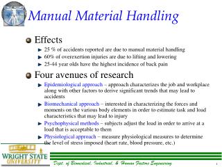
Introduction • Stress/Strain Concept • Workers affected by two types of forces • Immediate physical environment • Biomechanical forces of worker’s body • Both forces fundamental to basic ergonomics principles and described by the laws of Newtonian mechanics and biological laws of life (musculoskeletal and physiological systems response to task demands • Stress/Strain involves external forces and effort upon the worker which potential produces strain on worker’s musculoskeletal and physiological systems • Goal of ergonomicist is to reduce stress sufficiently to minimize musculoskeletal and/or physiological strain
MMH Stresses • Three approaches used • Biomechanical • Studies the musculoskeletal structure such that the physical, or mechanical, limits of the individual are determined. • Physiological • Studies the circulatory responses and the human body’s metabolic response to various loads. • Psychophysical • Establishes acceptable lifting weights to the individual. The individual subjectively quantifies his tolerance of stress (NIOSH, 1981)
Biomechanical Approach • Biomechanical Analysis for MMH • Definition and Applications • Biomechanics defined by Contini and Drillis (1966) as “the science which investigates the effect of internal and external forces on human and animal bodies in movement and at ‘rest’”. • Winter (1979) defined biomechanics of human movement as “the interdiscipline which describes, analyzes, and assesses human movements.” • Frankel and Nordin (1980) defined biomechanics as the discipline which “uses laws of physics and engineering concepts to describe motion undergone by the various body segments and the forces acting on these body parts during normal daily activities”
Figure 3.1 Schematic Diagram of biomechanics, modified from Contini and Drillis (1966)
Biomechanics Definitions(Continued) • General Biomechanics • Concerned with the fundamental laws and rules governing organic bodies at rest or in motion • Biostatics • Considers those situations in which only analysis of dobdies at rest or bodies moving in a straight line at uniform velocity (i.e., no acceleration generated, thus no force yield) is involved • Biodynamics • Concerned with the description of the movement of the body in time without consideration of the forces involved (kinematics) and motion caused by forces acting on the body (kinetics). • Both internal and external forces are included in kinetic analysis of motion
Occupational Biomechanics Definitions(Continued) • Division of applied biomechanics that involves applying the principles of biomechanics towards work in improving everyday activities, especially dealing with human disorders and performance limitations which exist at present in a variety of manual tasks in industry • Can be defined as “the study of the physical interaction of workers with their tools, machines, and materials so as to enhance the worker’s performance while minimizing the risk of musculoskeletal disorders” (Chaffin and Andersson, 1984)
The Body as a System of Levers • Biomechanics based on the disciplines of anthropometry, engineering science, bioinstrumentation, and kinesiology. • Requires criteria for application of measurements • Complexity of measurements and need for safety have resulted in extensive use of modeling • Modeling allows simplification, eliminates much of the experimentation and elaborate data collection/analysis
The Body as a System of Levers • Biomechanical approach requires evaluating the body as a system of links and connecting joints • Each link has the same length • Each link has the same mass and moment of inertia (Center of Mass) • Various researchers use various links; increases in computing power has increased complexity of modeling • Torso is often considered as a single or two-link system for simplicity although more complex modeling of the spine has been developed • Body segments rotated around joints by skeletal muscles; attachments of same are close to the joint • Small contractile distance transformed into large resistance and mechanical advantage; large muscle forces for small loads
Stress on the Musculoskeletal System • To estimate mechanical stress imposed on body while at rest or in motion, must use various mechanical properties of body segments to perform mechanical analysis • Simplification and assumptions necessary; use biomechanical models of various degrees of sophistication • Remember that forces are vector quantities with four characteristics: • Magnitude • Direction • Line of Action • Point of Application
Stress on the Musculoskeletal System • Three types of Forces on Total Body System • Gravitational Forces • Those forces acting through the center of mass of each segment with magnitude equal to the mass times gravitational acceleration • Ground Reaction or External Forces • Due to applied workload and body segment weights • Muscle Forces • Expressed in terms of net muscle moment acting at a joint. Some other forces such as joint friction and forces within the muscle also contribute to net moement
Static Analysis • Used to study the rotational moments and forces acting on the human body when no movement is involved • Physical forces can be analyzed as if executed statically (even when involve movement) • Dynamic considerations important (mechanically) only when motion involves significant linear or angular accelerations • If this is not the case, static analysis techniques are useful for studying static and quasi-static (quasi-isometric) physical activities
Analysis of One Segment Link • Example is forearm free body (see figure 3.3). • Assumes no significant joint exists • Assumes 8kg load held in hands • Load acting at hand produces a torque at elbow as does the weight of the forearm and hand • Involved muscles’ contractile activities produce necessary torque to counterbalance aforementioned torques • Since no body movement, static analysis is assumed
Analysis of One Segment Link(Continued) • Static Equilibrium • ∑ Moments (M) = 0; ∑ Forces (Fx or Fy) = 0 • Relative force and torque at elbow joint • Yt = 0 = W1 – Wa + Fy (Force equilibrium) Where : W1= the weight of the load; Wa = the weight of the forearm and hand; Fx = the reactive force at elbow joint in the x-direction; Fy = the reactive force at the elbow joint in the y-direction; Yt = the force in the Y direction; Xt = the force in the X direction.
Analysis of One Segment Link(Continued) • Reactive force at elbow joint in X direction with no force developed in horizontal direction is 0; • Reactive torque at elbow joint necessary to counterbalance forces produced by the load (weight & body segment x distances from Center of Rotation): • ∑M = 0 = -W1(D1) – Wa(Da) + ME Where: D1 = the length of the link; Da = the distance from the elbow to the link Center of Mass (CM) ME = the reactive moment at the elbow joint.
Analysis of One Segment Link(Continued) • Assume forearm no longer held horizontal but at angle as in figure 3.4 • Reduction in the moment arm • M = 0 = -W1(D1)(cos a) – Wa(Da) (cos a) + M1E Or • M1E = (cos a) x ME • So, the load and the weight of the arm has an additive effect on the elbow moment, with its maximum moment value when the arm is horizontal and a minimum effect when the arm is vertical
Analysis of Two Links • Effects of loads on hand and accumulated body segment weights transmitted to feet where reaction force takes place • Can treat two-link model as two separate one-link systems with same torque and force analyses • Static equilibrium condition, reactive forces and torque should be equal but opposite (distal end of the upper arm link)
Analysis of Two Links(continued) • Muscle group should produce force/torque at the shoulder joint to counteract force/torque of body segment and reactive force from previous link (calculated as 5.65kg) Yt = -2.1kg – 5.65kg +Rs Rs = 7.75kg And ∑M = 0 = -Wu(D2) – Re(Du) - ME + Ms = -2.1kg x (0.13m) – 5.65kg (0.33m) – 3.92kg – m + Ms Ms= 5.86kg – m
Analysis of Two Links(continued) • Arm posture changes have a great effect on the moments at the elbow and shoulder but no effect on external reactive force • Previous two-link model is effective, except vertical distance from point of rotation to action line of force is used to calculate moments (see figure 3.6)
Analysis of Multiple Links • Use same method to calculate reactive force and torque at each joint • Changes from the horizontal will change (increase or decrease) the moment but not the force. • Different posture can have different reactive moments and forces • Keep in mind Cartesian coordinate mapping systems and force terms (positive or negative).
Analysis of Internal Forces • Possible to look at models of internal muscles (see figure 3.8) • Resulting moment equation can be expressed as: ∑M = 0 = - W1(D1) – Wa(Da) + Fm(Dm) Where: ∑M = the sum of the moments about the elbow; Fm = the force due to muscular contraction; Dm = the distance from the elbow to the point of muscle action on the link;
Analysis of Internal Forces(continued) • Substituting those previous values into the above equation and isolating the unknowns produces: ∑M = 0 = - 4kg(0.36m) – 1.65kg(0.15m) +Fm(Dm) Fm(Dm) = 1.69kg-m • The torque of the muscle contraction must equal 1.69kg-m for the link to maintain static balance. If the value for Dm is assumed to be 0.05m, the magnitude of the muscle force can then be determined. Fm(0.5m) = 1.69kg – m Fm = 33.75 kg
Analysis of Internal Forces(continued) • Next, the horizontal and vertical force can be determined. Since there are no horizontal forces acting in this example, the horizontal force, Fx, drops out of the analysis. Substituting the known values into the following equation and isolating the unknown, Fy, produces the vertical force on the elbow. Yt = 0 = -W1 – Wa + Fy + Fm = - 4kg – 1.65kg + Fy + 33.75kg Fy = -28.1kg
Example 20kg Industrial Task • Assume frequently handled 20kg load • Creates a muscle contractile and vertical force at the elbow as follows: M = 0 = -10kg(0.36m) – 1.65kg(0.15m) + Fm(0.05m) Fm = 76.95kg Yt = 0 = -10kg – 1.65kg + Fy + 79.95kg Fy = -88.6kg • Demonstrates the forces sustained in holding common industrial load can be quite large.
Dynamic Analysis • See extensive notes on calculations of static and dynamic forces, moments as a function of various variables in notes • Note the effect of static versus dynamic loading • Note the effect of various angular (e.g., postural) changes on the overall loads (forces, moments, inertia) created when handling a relatively small weight • Notice how much more complicated the modeling becomes moving into a multivariable domain.