Momentum
Momentum. NEWTON’S LAWS. Newton’s laws are relations between motions of bodies and the forces acting on them. First law : a body at rest remains at rest, and a body in motion remains in motion at the same velocity in a straight path when the net force acting on it is zero.


Momentum
E N D
Presentation Transcript
NEWTON’S LAWS • Newton’s laws are relations between motions of bodies and the forces acting on them. • First law: a body at rest remains at rest, and a body in motion remains in motion at the same velocity in a straight path when the net force acting on it is zero. • Second law: the acceleration of a body is proportional to the net force acting on it and is inversely proportional to its mass. • Third law: when a body exerts a force on a second body, the second body exerts an equal and opposite force on the first.
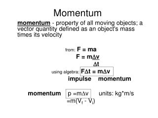
NEWTON’S LAWS AND CONSERVATIONOF MOMENTUM • For a rigid body of mass m, Newton’s second law is expressed as • Therefore, Newton’s second law can also be stated as the rate of change of the momentum of a body is equal to the net force acting on the body.
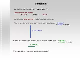
NEWTON’S LAWS AND CONSERVATIONOF MOMENTUM • The product of the mass and the velocity of a body is called the linear momentum. • Newton’s second law the linear momentum equation in fluid mechanics • The momentum of a system is conserved when it remains constant the conservation of momentum principle. • Momentum is a vector. Its direction is the direction of velocity. = Momentum
EXAMPLE 1-GRADUAL ACCELERATION OF FLUID IN PIPELINE • Q: Water flows through a pipeline 60m long at velocity 1.8m/s when the pressure difference between the inlet and outlet ends is 25 kN/m2. What increase of pressure difference is required to accelerate the water in pipe at rate 0.02 m/s2? • Solution: • Lets • A= cross-sectional of the pipe • l = length of pipe • ρ= mass density of water • a = acceleration of water • δp = increase in pressure at inlet required to produce acceleration A ρ δp a l
EXAMPLE 1- GRADUAL ACCELERATION OF FLUID IN PIPELINE • Note is steady flow state, consider a control mass comprising the whole of the water in the pipe. By Newton’s Second Law: • 1. Force due to δp,F = cross-sectional area x δp = A δp • 2. Mass of water in pipe,m = Density x Volume • = ρ x Al • 3. A δp = ρAl a • δp = ρl a • = 103 x 60 x 0.02 N/m2 • = 1.2 kN/m2
LINEAR MOMENTUM EQUATION • Newton’s second law for a system of mass m subjected to a force F is expressed as • During steady flow, the amount of momentum within the control volume remains constant. • The net force acting on the control volume during steady flow is equal to the difference between the rates of outgoing and incoming momentum flows.
LINEAR MOMENTUM EQUATION • Consider a stream tube and assume steady non-uniform flow A2 v2 ρ2 A1 v1 ρ1 v1
LINEAR MOMENTUM EQUATION In time δt a volume of the fluid moves from the inlet at a distance v1δt, so volume entering the stream tube = area x distance = A1 x v1δt The mass entering, mass entering stream tube = volume x density = ρ1A1v1δt And momentum momentum entering stream tube = mass x velocity = ρ1A1v1δt v1 Similarly, at the exit, we get the expression: momentum leaving stream tube = ρ2A2v2δt v2
LINEAR MOMENTUM EQUATION By Newton 2nd law Force = rate of change of momentum F = (ρ2A2v2δt v2 - ρ1A1v1δt v1) δt We know from continuity that Q= A1v1 = A2v2 And if we have fluid of constant density, ρ1 = ρ2 = ρ, then F = Qρ (v2-v1)
LINEAR MOMENTUM EQUATION An alternative derivation From conservation of mass mass into face 1 = mass out of face 2 we can write rate of change of mass = ˙ = dm/dt = ρ1A1v1 = ρ2A2v2 The rate at which momentum enters face 1 is ρ1A1v1 v1 = ˙ v1 The rate at which momentum leaves face 2 is ρ2A2v2 v2 = ˙ v2 Thus the rate at which momentum changes across the stream tube is ρ2A2v2 v2 - ρ1A1v1 v1 = ˙ v2 - ˙ v1 Force = rate of change of momentum F = ˙ (v2-v1) m m m m m m
LINEAR MOMENTUM EQUATION • So, we know these two expression. Either one is known as momentum equation: • F = ˙ (v2-v1) m F = Qρ (v2-v1) The momentum equation: This force acts on the fluidin the direction of the flow of the fluid
Momentum-Flux Correction Factor, b • Since the velocity across most inlets and outlets is not uniform, the momentum-flux correction factor, b, is used to patch-up the error in the algebraic form equation. Therefore, Momentum flux across an inlet or outlet: Momentum-flux correction factor:
LINEAR MOMENTUM EQUATION-STEADY FLOW • The net force acting on the control volume during steady flow is equal to the difference between the rates of outgoing and incoming momentum flows. Therefore, One inlet and one outlet
LINEAR MOMENTUM EQUATION-STEADY FLOW ALONG COORDINATE The previous analysis assumed the inlet and outlet velocities in the same direction i.e. a one dimensional system. What happens when this is not the case? We consider the forces by resolving in the directions of the co-ordinate axes. v2 v1
LINEAR MOMENTUM EQUATION-STEADY FLOW ALONG COORDINATE • The force in x-direction • Fx = ˙ (v2 cos θ2 – v1 cos θ1) • = ˙ (v2x– v1x ) • Or • Fx = ρQ (v2 cos θ2 – v1 cos θ1) • = ρQ (v2x– v1x ) • The force in y-direction • Fy = ˙ (v2 sin θ2 – v1 sin θ1) • = ˙ (v2y– v1y ) • Or • Fy = ρQ (v2 sin θ2 – v1 sin θ1) • = ρQ (v2y– v1y) • The resultant foce can be found by combining these components m m m m
SUMMARY Total Force on the fluid = rate of change of momentum through the control volume m F =β ˙ (vout - vin) F = βQρ (vout - vin) • Remember!!! • We are working with vectors so F is in the direction of the velocity
FORCE ACTING ON CONTROL VOLUME • Consist of two forces: • 1. Body forces • - such as gravity, electric, magnetic force • 2. Surface force • - such as pressure, viscous and reaction force • Total force acting on control volume is sum of body force and surface force.
FORCE ACTING ON CONTROL VOLUME • Force is made up of these component: • FR = force exerted on the fluid by any solid body touching the control volume • FB = Force exerted on the solid body (eg gravity) • FP = Force exerted on the fluid by fluid pressure outside the control volume • Total force is given by the sum of these three forces: • FT = FR + FB + FP • The force exerted by the fluid on the solid body touching the control volume is opposite to FR • So, the reaction force, R is given by • R = - FR
APPLICATION OF THE MOMENTUM EQUATION • FORCE DUE TO THE FLOW AROUND THE PIPE BEND • A converging pipe bend lying in the horizontal plane turning through an angle ofθ. A2 v2 ρ2 A1 v1 ρ1
FORCE DUE TO THE FLOW AROUND THE PIPE BEND • Why do we want to know the forces here? • As the fluid changes direction a force will act on the bend. • This force can be very large in the case of water supply pipes. • The bend must be held in place to prevent breakage at the joints. • We need to know how much force a support (thrust block) must withstand.
FORCE DUE TO THE FLOW AROUND THE PIPE BEND • Step in analysis • Draw a control volume • Decide on coordinate axis system • Calculate the total force • Calculate the pressure force • Calculate the body force • Calculate the resultant force
EXAMPLE 3- WATER JET STRIKING A STATIONARY PLATE • Q: Water accelerated by a nozzle to an average speed of 20 m/s and strikes a stationary vertical plate at rate of 10 kg/s with a normal velocity 20 m/s. After the strike, the water stream splatters off in all directions in the plane of the plate. Determine the force needed to prevent the plate from moving horizontally due to the water stream. Figure 3
EXAMPLE 3 • Solution: • Assumption • The flow of water at nozzle outlet is steady. • The water splatters in directions normal to the approach direction of the water jet. • β = 1 • We want to find the reaction force of the plate, so that the plate stay in the position.
EXAMPLE 3 • Step 1 & 2 : Control volume and Coordinate axis • shown in Figure 3 • Step 3: Calculate the total force • In the x-direction : • FTx = β˙ (v2x – v1x), • = β˙ v1x • = (1) (10 kg/s) (20 m/s) (1N/1kg.m/s2) = 200 N • The system is symetrical, the force in y-direction is not considered. • Step 4: Calculate the pressure force • The pressures at both the inlet and the outlets to the control volume are atmospheric. The pressure force is zero. • FPx =FPy =0 m m
EXAMPLE 3 • Step 5: Calculate the body force • As the control volume is small we can ignore the body force due to gravity. • FBx = FBy = 0 • Step 6: Calculate the resultant force • FRx = FTx – FPx – FBx • = 200 – 0 - 0 • = 200 N • The force on the plane is the same magnitude but in the opposite direction • R = - FRx = -200 N
Force on angle plane • If the plane were at an angle the analysis is the same. It is usually most convenient to choose the axis system normal to the plate.