Download
1 / 31
310 likes | 654 Vues
Relational Database Design: Converting Conceptual Models to Relational Databases. Chapter 6. Chapter Learning Objectives. Convert a conceptual business process level REA model into a logical relational model

E N D
Relational Database Design: Converting Conceptual Models to Relational Databases Chapter 6
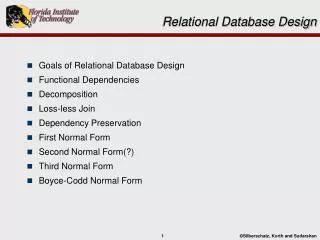
Chapter Learning Objectives • Convert a conceptual business process level REA model into a logical relational model • Convert a logical relational model into a physical implementation using Microsoft Access • Explain the difference between conceptual, logical, and physical database models • Enter transaction data into a relational database • Interpret a physical database implementation in Microsoft Access to determine what must have been the underlying logical model • Interpret a logical relational model to determine what the underlying conceptual model must have been • Recognize and implement various application level controls to facilitate the integrity of data entered into a relational database
Database Model Levels • A Conceptualmodel represents reality in an abstracted form • Hardware and software independent • Independent of any logical model type • A Logicalmodel represents reality in the format required by a particular database model • Hardware and software independent • Depends on the chosen logical model type • A Physicalmodel is created specifically for a particular database software package • Dependent on hardware, software • Dependent on the chosen logical model type
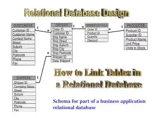
Relational Database Model • Based on set theory and predicate logic • A relational database consists of tables (relations) that are linked together via the use of primary and foreign keys • A FOREIGN KEY is a primary key from a different table that has been posted into the table to create a link between the two tables
Relational Database Model • Relational database tables are made up of rows and columns • Rows are called the table extension or tuples • The ordering of rows in a table does not matter • Columns are called the table intension or schema • The ordering of columns in a table does not matter • All values in a column must conform to the same data format (e.g. date, text, currency, etc.) • Each cell in a database table (a row-column intersection) can contain only one value • no repeating groups are allowed
Relational Database Model • Some principles of the relational model • Entity Integrity • A primary key in a table must not contain a null value • Guarantees uniqueness of entities and enables proper referencing of primary key values by foreign key values • Referential Integrity • A value for a foreign key in a table must either • Be null (blank) • Match exactly a value for the primary key in the table from which it was posted • One Fact, One Place • Fact = a pairing of a candidate key attribute value with another attribute value • Facts are found in the extensional data
2 4 1 3 1 3 2 4 One Fact-One Place Violations One fact in multiple places
One Fact-One Place Violations Multiple facts in one place 2 1 3 4 5
Converting Conceptual to Relational • Step 1: Create a separate table to represent each entity in the conceptual model • 1A: Each attribute of the entity becomes a column in the relational table • 2A: Each instance (member) of the entity set will become a row in the relational table
Relationship Conversion • Step 2: Create a separate table to represent each many-to-many relationship in the conceptual model • You must create a separate table to represent the relationship • The primary keys of the related entity tables are posted into the relationship table to form its primary key. This kind of primary key is called a composite or concatenated primary key • This avoids redundancy • There are no exceptions to this rule!!! • If you post a foreign key in either direction, redundancy will be a problem for many-to-many relationships
Relationship Conversion • Maximum Cardinalities • The general rule is to post into a “1” entity table • This avoids “repeating groups” redundancy • You can NEVER post into an “N” entity • This causes “repeating groups” redundancy • Minimum Cardinalities • The general rule is to post into a “1” (mandatory) entity table • This avoids null values in the foreign key column • This rule should be violated in some circumstances (to be discussed soon)
Relationship Conversion • Step 3: For participation cardinality pattern (1,1)-(1,1), consider whether the two entities are conceptually separate or whether they should be combined • If they should remain separate, then • 3A: Post the primary key from one entity’s table into the other entity’s table as a foreign key • DO NOT make a separate table
SaleID CR-ID Amount Amount Date Date Sale Cash Receipt (1,1) (1,1) yields Example: (1,1)-(1,1) Choose ONE of these; DO NOT do both!!!
Relationship Conversion • Step 4: For remaining relationships that have (1,1) cardinality pair in one entity set, post the related entity’s primary key into the (1,1) entity’s table as a foreign key • I.e., for the following cardinality patterns (0,N)-(1,1) (1,N)-(1,1) (1,1)-(0,N) (1,1)-(1,N) (0,1)-(1,1) (1,1)-(0,1) • Do NOT make a separate table • Post a foreign key INTO the (1,1) entity’s table from the other entity’s table
SaleID CustID City Amount Date Name Sale Customer (0,N) (1,1) Is-to S-ID* Cust-ID Name Address C1 Heather Walnut Creek C2 Steven Cincinnati Example 1: Posting into a (1,1) or (1,N)
SaleID CR-ID Amount Amount Date Date Sale Cash Receipt (0,1) (1,1) yields Example 2: Posting into a (1,1)
Relationship Conversion • Step 5: For remaining relationships that have (0,1) cardinality pair by one or both of the entities, consider loadI.e., for the following cardinality patterns (0,N)-(0,1) (1,N)-(0,1) (0,1)-(0,N) (0,1)-(1,N) (0,1)-(0,1) • The rule for maximum cards requires posting into a (0,1) or making a separate table • The rule for minimum cards says you shouldn’t post into the (0,1) • 5A: Post the related entity’s primary key into the (0,1) entity’s table as a foreign key for any relationships for which that results in a high load • 5B: Create a separate table for any relationships for which posting a foreign key results in low load • Note: For (0,1)-(0,1), step 5A, post whichever direction results in highest load; if neither direction yields high load, then follow step 5B
Some cash disbursements (13/26) pay for purchases If we post Receiving Report# into Cash Disbursement, 13 out of 26 will be non-null This is a medium load Might be worth breaking minimum rule Consider other posting option Most purchases (14/18) result in cash disbursements If we post Check# into Purchase, 14 out of 18 will be non-null This is a high load Worth breaking the minimum rule Example: Load Considerations
Few purchases (3/18) result in purchase returns If we post Purchase Return Slip# into Purchase, only 3 out of 18 will be non-null This is low load Must either make a separate table or consider posting the other direction Can’t post receiving report# into purchase return because one purchase return slip # can be associated with multiple purchases Example: Load considerations
Relationship Attribute Placement • If relationship becomes a separate table, then relationship attributes are placed in that table • If relationship can be represented by a posted foreign key, relationship attribute is posted alongside the foreign key
Relationship Attribute Placement • If relationship becomes a separate table, then relationship attributes are placed in that table • If relationship can be represented by a posted foreign key, relationship attribute is posted alongside the foreign key
Fixing One Fact Multiple Places Employee • What facts are in multiple places in this table? • Reverse engineer to get the ER model that this table must represent • Is the ER model that results in this table correct? • What SHOULD the ER model have been instead? • What is the correct relational model?
EmplID DeptID Department Employee Empname DeptName Assigned to Payrate HoursWorked Fixing One Fact Multiple Places Department Employee
Fixing Multiple Facts in One Place Warehouse InventoryInWarehouse • What facts are in multiple places? • How could this be avoided? Inventory
Fixing Multiple Facts in One Place Warehouse InventoryInWarehouse Inventory
Relationships between tables versus relationships between entities
Summary • The relational model is based on set theory and predicate logic and the resultant relations (tables) can be manipulated for information retrieval purposes if they are properly constructed • To create well-behaved tables, follow the rules we discussed • Conversion rules for cardinality patterns • One Fact-One Place • Think at the data (extensional) level!! • When creating physical databases, use the conceptual and logical models to help you realize the important issues and potential pitfalls