
G30 Relay Application & Configuration
G30 Relay Application & Configuration. Craig Wester GE Multilin. g. imagination at work. G30 is Member of UR Relay Family. The UR Family A Common Hardware/Software Architecture. Modular Construction Reduces Part Inventory. Generation Protection G30 – Generator & Transformer Protection

G30 Relay Application & Configuration
E N D
Presentation Transcript
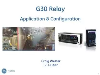
G30 Relay Application & Configuration Craig WesterGE Multilin
g imagination at work G30 is Member of UR Relay Family
The UR FamilyA Common Hardware/Software Architecture Modular Construction Reduces Part Inventory
Generation Protection G30 – Generator & Transformer Protection G60 – Generator Protection Transformer Protection T35 – Transformer Protection (6 winding) T60 – Transformer Protection Transmission Line ProtectionL60 – Line Phase Comparison Protection L90 – Line Differential Protection D30 – Backup Distance Protection D60 – Line Distance Protection (pilot schemes) Bus Protection B30 – Bus Differential Protection (6 Circuits) B90 – Bus Differential System (8 to 24 Circuits) F35+HID – High Impedance Bus Differential F35 – Bus Overcurrent Protection Feeder Protection F35 – Feeder Protection (1-6 feeders) F60 – Feeder Protection (with Hi-Z) Capacitor Bank ProtectionC70 – Capacitor Bank Protection & Control Motor Protection M60 – Motor Protection Network Protection N60 – Network Protection and Synchrophasors (4 PMU’s) Controllers C30 – Controller C60 – Breaker Management
Topics • Overview of application • ANSI functions in relay needed for application • Modules needed • Creating the part number • Wiring to modules • Terminals • Voltage monitoring • Current monitoring • Programming the relay • Protection summary • Trip Bus • FlexLogic • Viewpoint Engineer
g imagination at work Overview of Application
Single-Line DiagramWith Step-Up TransformerMain Generator Protection uses Transformer High-side CTs & PTs 1, 2 or 3 3 2 or 3 87RGF Y 1 3 87GT 1
Single-Line DiagramNo Step-up TransformerMain Generator Protection Assigned to Generator Terminal CTs & PTs 3 1, 2 or 3 2 or 3 87GT 3 87RGF 1
g imagination at work Modules Needed & Model Number Selection
Model: G30-N00-HLH-F8L-H6P-M8L-P5C-UXX-WXX Horizontal Model Number Structure
Model: G30-N00-VLH-F8L-H6P-M8L-PXX Vertical Model Number Structure
g imagination at work Module Details & Wiring
Local Control/Display (Type L Faceplate) • Backlit Keypad • 16 Large User Programmable Pushbuttons • 3 Small User Programmable Pushbuttons • Status LED for Each Pushbutton • Eliminates Existing Panel Control Switches
Rear Terminals of Horizontal G30 Relay Example Model: G30-N00-HLH-F8L-H6P-M8L-P5C-UXX-WXX I/O (6P) CPU Pwr Supply 4CT (M1) 4CT (F1) RTD(5C) 4VT (M5) 4VT (F5)
Rear Terminals of Vertical G30 Relay Example Model: G30-N00-VLH-F8L-H6P-M8L-PXX
Power Supply Module Power Supply Power Supply • Two Ranges • 19-60 VDC (L) • 88-300 VDC / 88-288 VAC (H) • Battery for Memory Backup Control Power: B6b-B6a 24Vdc B5b-B6a 125Vdc Grounds B8a, B8b, Chassis Gnd
CPU Module CPU CPU Main Processor • High-speed 32-Bit RISC CPU • > 50 MIPS, up to 120 MIPS • (MIPS - Million Instructions per Second)FLASH memory • Easy firmware upgrades • High-Speed Comms support • 10/100 Mbps Ethernet LAN • RS485 • IRIG-B Input • Capacitor Memory Backup Ethernet Port
Communication Protocols • Internet/Intranet Ready - IP Address • Simple Network Time Protocol (SNTP) for Real Time Clock Synchronization • Modbus RTU protocol • Standard Front Port: RS232 (point-to-point) • Rear Ports: RS485 up to 115kbps, 10/100BaseT (Ethernet) or 10/100BaseF (Fiber Optic) • Available over TCP/IP • DNP 3.0 Protocol (CERTIFIED) • Rear Ports: RS485 up to 115kbps and 10/100BaseT/F Ethernet • IEC61850 protocol (optional) • Physical: 10/100BaseT (Ethernet) or 10/100BaseF (Fiber Optic) • Available Only on CPUs with Ethernet Port(s) • HTML View Access with Netscape or Internet Explorer • Ethernet Connections DNP, Modbus, IEC61850 protocols simultaneously available on Ethernet port
CT/VT Modules (Type 8L) M F F F F F F F F F F F F F F M M M F M F F F F M M M M F M M M M M M M M M M M DSP + CT/VT DSP & Magnetics DSP processor + CT/VTs • Modular CT/VT configurations • up to 8 CT/VTs • High-speed digital sampling • >16 Bit A/D converter • > 64 samples / cycle • High-speed 16-Bit DSP • > 32 MIPS, up to 80 MIPS • “Sources” Concept • User Selects CT/VT Input for • Protection Element CT Shorting Clip CT Shorting Clip
Input/Output Modules Digital I/O DIGITAL I/O Status Inputs / Control Outputs • Many Module Choices • 2 Form A, 2 Form C and 8 Inputs • 2 Form A, 4 Form C and 4 Inputs • 8 Form C Outputs • 4 Form C, 8 Inputs • 8 Fast Form C • 6 Form A, 4 Inputs • 16 Inputs • 4 Form A, 8 Inputs (6N) • 4 Form C, 8 Inputs (6P) • 4 Form C, 4 Fast Form C • 14 Latching Relays • Transducer I/O • 8 dcmA • 8 RTD inputs (5C) • 4 dcmA & 4 RTD • Digital Inputs Flexibility • Dry or Wet Type (48 Vdc provided by relay) • Minimum Pickup Value Software Setting • 17, 33, 84 or 166 Vdc • Digital Output Monitoring • Current and Voltage Monitoring of Trip & Close Circuits • Control outputs • Solid State • Electromechanical - multiple types • Fast activation (< 4ms) • Status inputs • Dry and Wet contacts • 18 - 300 VDC • Fast detection speeds • (0.5-16ms Selectable)
Input/Output Module (6P module in “H” slot) H H H H H H H H H H H H H H H H H H H H H H H H H H H H H H H H H H H
Input/Output Module (6N module in “H” slot) H H H H H H H H H H H H H H H H H H H H H H H H H H H H H H H H H H H H H
Contact Input Wiring Contact Inputs are polarity sensitive
dcMA or RTD Inputs/Outputs P P P P P P P P P P P P P P P P P P P P P Analog I/O ANALOG I/O Analog Transducer I/O • Transducer type inputs & outputs • dcmA • RTD RTD Inputs (Type 5C) 26
Rear Terminals of G30 Relay Example Model: G30-N00-HLH-F8L-H6P-M8L-P5C-UXX-WXX I/O (6P) CPU Pwr Supply 4CT (M1) 4CT (F1) RTD(5C) 4VT (M5) 4VT (F5)
Metering & Monitoring • Current (Phase, Neutral and Ground) - [mag & ang] • Accuracy: ± 0.25% of reading or ± 0.1% of rating from 0.1 to 2.0 x CT rating (whichever is greater) • Voltage (Vab Vbc Vca Van Vbn Vcn) - [mag& ang] • Accuracy: ± 0.25% of reading from 10 to 208 V • Sequence Components of I & V • I0, I1, I2, V0, V1, V2 • Apparent Power (VA) - 1ph & 3ph • Accuracy: ± 1.0% of reading • Real Power (Watts) - 1ph & 3ph • Accuracy: ± 1% of reading • Reactive Power (Vars) - 1ph & 3ph • Accuracy: ± 1% • Power Factor - 1ph & 3ph • Accuracy: ± 0.02 • Energy (Pos & Neg Wh, Varh) - 3ph • Frequency • Differential Currents • Synchrocheck (V, Hz, Mag) • Phasor Diagrams
Programmable LEDs and Labels Easy Labeling Large Label Text Large LED’s
g imagination at work Programming Relay
GE Multilin Software • EnerVista UR Setup • Manages communications to all relays • Retrieves event logs, fault reports, oscillography • Settings file firmware management and firmware management • Lock configurations for repeatability • ViewPoint Engineer • FlexLogic Editor to create logic using a graphical interface • FlexLogic Monitor for real-time debugging/testing/commissioning
Functional Diagram CT & VT Inputs Remote Inputs IEC61850 GSSE IEC61850 GOOSE IEC61850 GSSE IEC61850 GOOSE
EnerVista: Setup Software . . . Simplified Device Configuration • Settings Configuration: • Communicate with multiple relays at the same time • Configure settings both On-Line and Offline • Copy and paste settings • Duplicate settings files • Easy to navigate menu tree • Quick connect communications • Common look and feel for all products • Metering: • Status of all inputs and outputs • Real-time metering with phasor diagrams • Analyzing of current and voltage harmonics • Viewing of relay front panel • Troubleshooting & Maintenance: • Analyzing of event records • Powerful oscillography COMTRADE viewer • Real time data logging and fault reports • Compare relay settings with setting file • Upgrade firmware
Protection Summary . . . Quickly Lists which Protection Functions are Enabled and Gives Link to That Function
Trip Bus – Set Relay without Using Logic . . . 16 input OR gate….up to 6 TRIP BUS elements can be configured
Sources and Transformer Configuration Note CT polarities in Typical Wiring Diagram and connections to G30. These are necessary to correctly meter forward power. The transformer phase shift setting must compensate the measured relay currents for both the actual phase shift of the transformer, and any phase due to the CT polarities and connections.
Sources and Transformer Configuration Assumption: Step-up Transformer is -30° lagging (from line side to generator side) Sources to match Typical Wiring Diagram: Transformer Configuration
Single-Line DiagramWith Step-Up TransformerMain Generator Protection uses Transformer High-side CTs & PTs F8 1, 2 or 3 F1-F3 3 2 or 3 F5-F7 87RGF Y 1 M1-M3 3 87GT M4 1
Programmable Logic - Viewpoint Engineer . . . Design Ease and Productivity Improvement • Graphical Flexlogic Editor • Create logic using a graphical editor • Document logic and store documentation in setting file • Detects errors commonly made in logic creation • Allows for configuration through to elements, I/O, LEDs, etc. • Capability to build and organize logic on separate worksheets • Graphical Flexlogic Analyzer • Analyze the status of Flexlogic in Real-Time • Easily detect problems in wiring • Simplify commissioning by easily following status of logic on the screen
Graphical Programmable Logic Designer . . . Customized Control and Operation Logic
“Click To” Protection Elements for Editing . . . Reduces Engineering and Setting File Creation Time
Dynamic Logic Monitor . . . Aids in Troubleshooting and Reduces Installation Time • Highlights show asserted logic