Pipelining Part I
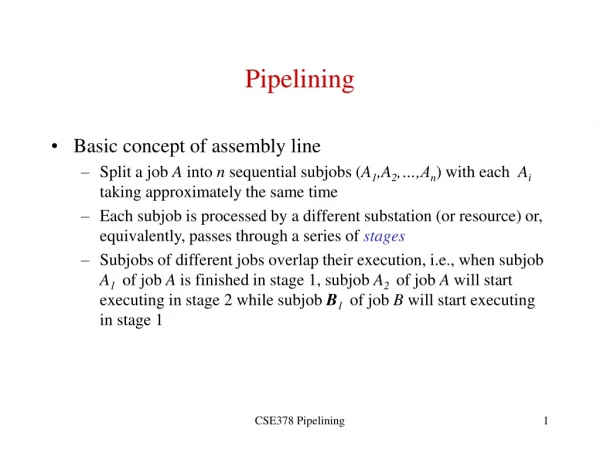
Pipelining Part I. CS448. F1. D1. E1. F2. D2. E2. F3. D3. E3. What is Pipelining?. Like an Automobile Assembly Line for Instructions Each step does a little job of processing the instruction Ideally each step operates in parallel Simple Model Instruction Fetch Instruction Decode


Pipelining Part I
E N D
Presentation Transcript
Pipelining Part I CS448
F1 D1 E1 F2 D2 E2 F3 D3 E3 What is Pipelining? • Like an Automobile Assembly Line for Instructions • Each step does a little job of processing the instruction • Ideally each step operates in parallel • Simple Model • Instruction Fetch • Instruction Decode • Instruction Execute
Ideal Pipeline Performance • If stages are perfectly balanced: • The more stages the better? • Each stage typically corresponds to a clock cycle • Stages will not be perfectly balanced • Synchronous: Slowest stage will dominate time • Many hazards await us • Two ways to view pipelining • Reduced CPI (when going from non-piped to pipelined) • Reduced Cycle Time (when increasing pipeline depth)
Ideal Pipeline Performance • Implemented completely in hardware • Exploits parallelism in a sequential instruction stream • Invisible to the programmer! • Not so for other forms of parallelism we will see • Not invisible to programmer looking to optimize • Compiler must become aware of pipelining issues • All modern machines use pipelines • Widely used in 80’s • Multiple pipelines in 90’s
DLX Instructions I-Type 6 5 5 16 Opcode rs1 rd Immediate Loads & Stores rd rs op immediate Conditional Branches rs1 is the condition register checked, rd unused, immediate is offset Mostly just look at I-Type for now R-Type and J-Type 6 5 5 5 11 Opcode rs1 rs2 rd func Opcode Offset added to PC
Unpipelined DLX • Every DLX instruction can be executed in 5 steps • 1. IF – Instruction Fetch • IR Mem[PC] • NPC PC + 4 ; Next Program Counter • 2. ID – Instruction Decode / Register Fetch • A Regs[IR6..10] ; rs1 • B Regs[IR11..15] ; rd • Imm (IR16)16 ## IR16..31 ; Sign extend immediate • Fetch operands in parallel for later use. • Might not be used! • Fixed Field decoding
Unpipelined DLX • 3. EX - Execution / Effective Address Cycle • There are four operations depending on the opcode decoded from the previous stage • Memory Reference • ALUOutput A + Imm ; Compute effective address • Register-Register ALU Operation • ALUOutput A func B ; e.g. R1 + R2 • Register-Immediate ALU Operation • ALUOutput A op Imm ; e.g. R1 + 10 • Branch • ALUOutput NPC + Imm ; PC based offset • Cond A op 0 ; e.g. op is == for BEQZ • Note that the load/store architecture of DLX means that effective address and execution cycles can be combined into one clock cycle since no instruction needs to simultaneously calculate a data address and perform an ALU op
Unpipelined DLX • 4. MEM – Memory Access / Branch Completion • There are two cases, one for memory references and one for branches • Both cases • PC NPC ; Update PC • Memory reference • LMD Mem[ALUOutput] ; for memory Loads • Mem[ALUOutput] B ; or Stores • Note the address was previously computed in step 3 • Branch • If (cond) PC ALUOutput ; PC gets new address
Unpipelined DLX • 5. WB – Write Back • Writes data back to the REGISTER FILE • Memory writes were done in step 4 • Three options • Register to Register ALU • Regs[IR16..20] ALUOutput ; rd for R-Type • Register-Immediate ALU • Regs[IR11..15] ALUOutput ; rd for I-Type • Load Instruction • Regs[IR11..15] LMD ; LMD from 4
Hardware Implementation of DLX Datapath Registers between stages Pipelined
Unpipelined DLX Implementation • Most instructions require five cycles • Branch and Store require four clock cycles • Which aren’t needed? • Reduces CPI to 4.83 using 12% branch, 5% store frequency • Other optimizations possible • Control Unit for five cycles? • Finite State Machine • Microcode (Intel)
Why do we need Control? • Clock pulse controls when cycles operate • Control determines which stages can function, what data is passed on • Registers are enabled or disabled via control • Memory has read or write lines set via control • Multiplexers, ALU, etc. must be selected • COND selects if MUX is enabled or not for new PC value • Control mostly ignored in the book • We’ll do the same, but remember… it’s a complex and important implementation issue
Adding Pipelining • Run each stage concurrently • Need to add registers to hold data between stages • Pipeline registers or Pipeline latches • Rather than ~5 cycles per instruction, 1 cycle per instruction! • Ideal case: • Really this simple? • No, but it is a good idea… we’ll see the pitfalls shortly
Important Pipeline Characteristics • Latency • Time required for an instruction to propagate through the pipeline • Based on the Number of Stages * Cycle Time • Dominant if there are lots of exceptions / hazards, i.e. we have to constantly be re-filling the pipeline • Throughput • The rate at which instructions can start and finish • Dominant if there are few exceptions and hazards, i.e. the pipeline stays mostly full • Note we need an increased memory bandwidth over the non-pipelined processor
Pipelining Example • Assume the 5 stages take time 10ns, 8ns, 10ns, 10ns, and 7ns respectively • Unpipelined • Ave instr execution time = 10+8+10+10+7= 45 ns • Pipelined • Each stage introduces some overhead, say 1ns per stage • We can only go as fast as the slowest stage! • Each stage then takes 11ns; in steady state we execute each instruction in 11ns • Speedup = UnpipelinedTime / Pipelined Time = 45ns / 11ns = 4.1 times or about a 4X speedup Note: Actually a higher latency for pipelined instructions!
Pipelining Hazards • Unfortunately, the picture presented so far is a bit too good to be true… we have problems with hazards • Structural • Resource conflicts when the hardware can’t support all combinations of overlapped stages • e.g. Might use ALU to add PC to PC and execute op • Data • An instruction depends on the results of some previous instruction that is still being processed in the pipeline • e.g. R1 = R2 + R3; R4 = R1 + R6; problem here? • Control • Branches and other instructions that change the PC • If we branch, we may have the wrong instructions in the pipeline
Structural Hazards • Overlapped execution may require duplicate resources • Clock 4: • Memory access for i may conflict with IF for i+4 • May solve via separate cache/buffer for instructions, data • IF might use the ALU which conflicts with EX
Dealing with Hazards • One solution: Stall • Let the instructions later in the stage continue, and stall the earlier instruction • Need to do in this order, since if we stalled the later instructions, they would become a bottleneck and nothing else could move out of the pipeline • Once the problem is cleared, the stall is cleared • Often called a pipeline bubble since it floats through the pipeline but does no useful work • Stalls increase the CPI from its ideal value of 1
Structural Hazard Example • Consider a CPU with a single memory pipeline for data and instructions • If an instruction contains a data memory reference, it will conflict with the instruction fetch • We will introduce a bubble while the latter instruction waits for the first instruction to finish
Structural Hazard Example No Instr finished in CC8 What if Instruction 1 is also a LOAD?
Avoiding Structural Hazards • How can we avoid structural hazards? • Issue of cost for the designer • E.g. allow multiple access paths to memory • Separate access to instructions from data • Build multiple ALU or other functional units • Don’t forget the cost/performance tradeoff and Amdahl’s law • If we don’t encounter structural hazards often, it might not be worth the expense to design hardware to address it, instead just handle it with a stall or other method
Measuring Performance with Stalls We also know that: Substitution Yields:
Measuring Stall Performance Given: We can calculate CPI_Pipelined: The ideal CPI is just the value 1. Substituting this in: Assuming no overhead in pipelined clock cycles (i.e. the latch time) then the clock cycle ratio is just 1, yielding:
How Realistic is the Pipeline Speedup Equation? • Good for a ballpark figure, comes close to a SWAG • Overhead in pipeline latches shouldn’t be ignored • Effects of pipeline depth • Deeper pipelines have a higher probability of stalls • Also requires additional replicated resources and higher cost • Need to run simulations with memory, I/O systems, cache, etc. to get a better idea of speedup • Next we’ll examine the myriad of problems from data hazards and control hazards to further complicate our simple pipeline