ERCOT SOL Methodology for the Planning and Operations Horizons
330 likes | 642 Vues
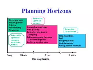
ERCOT SOL Methodology for the Planning and Operations Horizons. Stephen Solis 2014 OTS. Objectives. At the completion of this course of instruction you will: Identify the purpose of the ERCOT SOL methodology. Identify the related NERC Standards

ERCOT SOL Methodology for the Planning and Operations Horizons
E N D
Presentation Transcript
ERCOT SOL Methodology for the Planning and Operations Horizons Stephen Solis 2014 OTS
Objectives • At the completion of this course of instruction you will: • Identify the purpose of the ERCOT SOL methodology. • Identify the related NERC Standards • Identify what is a System Operating Limit (SOL) • Identify what is an Interconnection Reliability Operating Limits (IROL) • Identify relationships and impacts between ERCOT and Transmission Planners/Transmission Operators
Purpose of ERCOT SOL Methodology • Ensure System Operating Limits (SOLs) are determined based on an established methodology • Describes the methodology for determining Interconnection Reliability Operating Limits (IROLs) • Documents communications
Why did it change? • Recommendations from Texas Reliability Entity in 2012 • 2011 Arizona/San Diego Blackout. • To increase clarity. • To improve on the criteria for determination of IROLs. • Combined the planning and operations horizon SOL methodologies for consistency and ensuring review of changes
2011 Arizona/San Diego Blackout 18 Failure to recognize Interconnection Reliability Operating Limits and Establish Valid System Operating Limits 24 Not Recognizing Relay Settings When Establishing SOLs
Related NERC Standards • System Operating Limits Methodology for the Planning Horizon : FAC-010-2.1 • System Operating Limits Methodology for the Operations Horizon: FAC-011-2 • Establish and Communicate System Operating Limits: FAC-014-2
FAC-010-2.1 • Applicable to Planning Authority only • R1 – R3 detail what the methodology must contain and address. • R4 details who the methodology must be distributed to. • R5 details the requirement to respond to comments within 45 calendar days (retired as part of “paragraph 81" efforts)
FAC-011-2 • Applicable to Reliability Coordinator only • Same requirements as FAC-010-2.1
FAC-014-2 • Applicable to RC, PA, TP, and TOP • R1 – R4: establishSOLs/IROLsconsistent with the methodology • R5: Provide SOLS/IROLsto those with need • R6: PAcommunicatemultiple contingencies resulting in stability limitsto the RC.
What is a SOL? • The value (such as MW, MVar, Amperes, Frequency or Volts) that satisfies the most limiting of the prescribed operating criteria for a specified system configuration to ensure operation within acceptable reliability criteria. System Operating Limits are based upon certain operating criteria. These include, but are not limited to: • Facility Ratings (Applicable pre- and post-Contingency equipment or facility ratings) • Transient Stability Ratings (Applicable pre- and post- Contingency Stability Limits) • Voltage Stability Ratings (Applicable pre- and post- Contingency Voltage Stability) • System Voltage Limits (Applicable pre- and post- Contingency Voltage Limits)
What is a SOL? • Several limits ensure operation within acceptable reliability criteria • Facility ratings are the majority of the SOLs. • Typically, the most restrictive • Stability limits or Interface limits constitute additional SOLs • may be the most restrictive
What is a SOL? • Example 1: • Line A to B 138kV has a thermal facility rating of 100 MVA continuous rating. • Line A to B 138kV has a voltage stability limit of 150 MVA • Line A to B 138kV has a dynamic stability limit of 130 MVA • What is its System Operating Limit? Answer: Line A to B 138kV has a thermal facility rating of 100 MVA continuous rating which is the most restrictive of the limits and is thus the System Operating Limit.
What is a SOL? • Example 2: • Line A to B 138kV has a thermal facility rating of 100 MVA continuous rating. • Line A to B 138kV has a voltage stability limit of 90 MVA • Line A to B 138kV has a dynamic stability limit of 130 MVA • What is its System Operating Limit? Answer: Line A to B has a voltage stability limit of 90 MVA which is the most restrictive of the limits and is thus the System Operating Limit.
What is a SOL? • Example 3: • Line A to B 138kV has a thermal facility rating of 100 MVA Normal (Continuous) rating. • Line A to B 138kV has a thermal facility rating of 120 MVA Emergency (2 hour) rating. • Line A to B 138kV has a thermal facility rating of 140 MVA 15 minute (Load Shed) rating. • What is its System Operating Limit? Answer: All of the above. Each facility rating is a System Operating Limit with an associated time frame. The facility can be operated at 100 MVA continuously, up to 120 MVA for up to 2 hours, and up to 140 MVA for up to 15 minutes.
Steady State Voltage SOLs • Steady State Voltage SOLs in ERCOT: • (1) 0.95 per unit to 1.05 per unit in the pre-contingency state (and with all facilities in service in the planning horizon) • (2) 0.90 per unit to 1.10 per unit in the post-contingency state (following a NERC Category B or C contingency (where appropriate) • These are default unless otherwise communicated by the Facility Owner.
Additional SOLs • Result from studies indicating a more restrictive limit that results in the following: • Transient, dynamic instability • (loss of a generator due to the instability) • Voltage instability • (uncontrolled voltage loss) • Cascading or uncontrolled separation; • Post disturbance frequency • outside the range 59.4 Hz to 60.4 Hz
Additional SOLs (continued) • Manual system adjustments, • e.g., system reconfiguration between contingencies in an N-1-1 Category C event, or load shedding are needed in order to prevent Cascading or transient, dynamic, or voltage instability.
Additional SOLs (continued) • Voltage stability margin in the planning horizon is not sufficient to maintain post-transient voltage stability under the following two conditions for an ERCOT or TP-defined area: • A 5% increase in Load above expected peak supplied from resources external to the ERCOT or TP-defined area and NERC Category A or B operating conditions; or • A 2.5% increase in Load above expected peak supplied from resources external to the ERCOT or TP-defined area and NERC Category C operating conditions;
Sub Bulk Electric System(BES) facilities • In ERCOT, 69kV facilities are considered transmission and are monitored and secured. • The SOL methodology applies to BES facilities. • Non-BES facilities and contingencies can be evaluated for their effect in determining a SOL on BES facilities. • Non-BES facilities have limits that are enforced, just not SOLs as defined by NERC.
When is a SOL and IROL? • Interconnection Reliability Operating Limit (IROL) • SOL that, if violated, could lead to: • instability, • uncontrolled separation, or • Cascading Outages • Cascading • Uncontrolled successive loss of system elements • widespread electric service interruption that cannot be restrained from sequentially spreading beyond an area predetermined by studies.
When is a SOL an IROL? • An SOL is an IROL if: • Loss of load (manual or auto) is greater than 6% of the ERCOT Interconnection load level used in the study • Triggers automatic under-frequency load shedding • Observable inter-area oscillation with damping ratio less than 3%.
Where did the 6% come from? • Previous SOL methodologies used a 20% load threshold and exercised engineering judgment when the loss of load in a study was less than 20%. • 6% is a conservative value so that a loss of load should not cause generation to begin tripping off as a result of the loss of load (over-frequency). • ERCOT Operating Guides Section 2.6.2 requires no automatic tripping below 60.6 Hz. • Any set points between 60.6Hz and 61.6Hz should not trip within 9 minutes.
Load Loss in Study Current Version Previous Versions Load Loss in Study Load Loss in Study 20% IROL Defend why a SOL with a consequence of load loss greater than 6% is not an IROL Engineering Judgment Defend why a SOL with less than 20% load loss should be an IROL. IROL 6%
ERCOT ISO and Transmission Planners/Transmission Operators • ERCOT ISO: • single RC and PA for the ERCOT Interconnection. • distributesthis methodology to all TPs and TOPs in the ERCOT Interconnection. • establishesSOLs in accordance with the SOL methodology. • respondstocommentson the SOL methodology. • providesSOLs(including IROLs) to TOPs and TPs in the ERCOT Interconnection that provide a written request that includes a schedule for delivery of those limits.
ERCOT ISO and Transmission Planners/Transmission Operators • TPs and TOPs • establish SOLs in accordance with the SOL methodology. • provide any SOLs to ERCOT ISO. • Facility Ratings • Special Transfer Limits • Stability Limits • should incorporate any SOLs that are provided to them by ERCOT ISO or adjacent entities that affect their area into their studies for determining SOLs. • TPs provide SOLs to adjacent TPs and TOPs
Summary • The SOL Methodology ensures that SOLs used in the reliable operation of the ERCOT System are determined based on an established methodology. • The SOL is the most restrictive of all ratings or limits on a BES facility or element. • IROLs are the subset of SOLs that meet the IROL criteria. • SOLs are distributed amongst TPs, TOPs, and ERCOT ISO.
References • 1.) NERC Glossary of Terms • http://www.nerc.com/pa/Stand/Glossary%20of%20Terms/Glossary_of_Terms.pdf • 2.) NERC Reliability Standards • http://www.nerc.com/pa/Stand/Reliability%20Standards%20Complete%20Set/RSCompleteSet.pdf • 3.) ERCOT Operating Guides • http://www.ercot.com/content/mktrules/guides/noperating/2013/1007/October_7,_2013_Nodal_Operating_Guides.pdf • 4.) Arizona-Southern California Outages on September 8, 2011 • http://www.ferc.gov/legal/staff-reports/04-27-2012-ferc-nerc-report.pdf • 5.) ERCOT System Operating Limit Methodology for the Planning and Operations Horizon • http://planning.ercot.com/login/login (Home > Procedures > Planning Horizon Limits Documents. )
Questions ? ?
1. The purpose of the ERCOT SOL methodology is to ensure System Operating Limits (SOLs) is determined based on a ______________ ______________? • established methodology • load forecast • network model • increased clarity
Which of the following NERC related standards are applicable to System Operating Limits (SOLs)? • FAC-010-2.1 • FAC-011-2 • FAC-014-2 • All of the above
____________ ratings are the majority of the System Operating Limits (SOLs) and are typically the ________ restrictive. • Facility; most • Generator; most • Wave trap; least • Insulator; most
An SOL is an IROL if loss of load (manual or automatic) is greater than _________ of the ERCOT interconnection load level used in the study. • 4% • 3% • 5% • 6%
ERCOT ISO ___________ SOLs in accordance with the SOL methodology. • establishes • collects • protects • auctions