Download

1 / 61
610 likes | 806 Vues
Preventing Denial of Service Attacks. by N.V.Krishna Rao (08034D0501) Under Supervision and Guidance of Dr. S.Durga Bhavani S.V.S.Hanumantha Rao (Internal Guide) (External Guide). ABSTRACT(MDAF Scheme):

E N D
Preventing Denial of Service Attacks by N.V.KrishnaRao (08034D0501) Under Supervision and Guidance of Dr. S.DurgaBhavaniS.V.S.HanumanthaRao (Internal Guide) (External Guide)
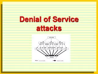
ABSTRACT(MDAF Scheme): This Project proposes a scheme for detecting and preventing the most harmful and difficult to detect DoS Attacks those that use IP address spoofing to disguise the attack flow. The scheme allows the system to configure itself based on the normal traffic of a Web server, so that the occurrence of an attack can be quickly and precisely detected. The MDAF scheme scans the marking field of all incoming packets to selectively filter-out the attack packets. On employing this marking scheme, when a packet arrives at its destination, its marking depends only on the path it has traversed. If the source IP address of a packet is spoofed, this packet must have a marking that is different from that of a genuine packet coming from the same address. The spoofed packets can thus be easily identified and dropped by the filter, while the legitimate packets containing the correct markings are accepted.
Existing System: Approaches for Defending DoS Attacks Preventive Source Tracking Reactive Defense Solutions Proactive Server - Packet Marking Schemes Path Identifier scheme (Pi) Roaming Scheme Probabilistic Packet Marking(PPM) Pushback method Deterministic Marking Approach(DPM) D-WARD Message Traceback Method Packet Score Logging Neighbor Stranger- Traffic Observation Method Discrimination (NSD)
Proposed System: • Distinguishing the Attack Packets • Learning Phase • Filtering Phase • Marking Verification • Attack Detection • Complete Filtering Scheme • Route Change Consideration • Pushback Implementation
Distinguishing the Attack Packets • Marking Scheme: Marking algorithm: k <- a 16-bit random number, secretly maintained by the Router M(R) <- k XOR h(A) For each packet w { If W.ID = 0 Then w.ID <- M(R) Else { M_old <- w.ID M_new <- M(R) XOR SL(M_old) w.ID <- M_new } }
Learning Phase The (IP-address, Marking) pairs are stored in a Filter Table, which are later used to verify each incoming packet and filter-out the spoofed ones. • Filtering Phase To the packet from an IP address recorded in the Filter Table, it is accepted if it has a consistent marking otherwise, it is dropped . For the packet from a new IP address, scheme accept it with probability p and put the (IP-address, Marking) pair to a Check List, so that the marking can be verified. • Marking Verification If there is a consistent marking from unknown IP address till the threshold value then the (IP-address, Marking) from check table is moved to Filter table. • Attack Detection A counter known as TMC is maintained by server, it is incremented each time packets with incorrect markings as well as packets from unknown source addresses that are not recorded if counter reaches the threshold value then attack is signaled.
Complete Filtering Scheme: • If the (IP-address, Marking) pair is same with one of the records in the Filter Table, the packet is received. • 2) If the source IP address of the packet exists in theFilter Table, but the marking does not match, this packet is considered to be a spoofed packet and is dropped. TMC is incremented. • 3) If the source IP address does not appear in the Filter Table, then this packet is accepted with a probability p. TMC is incremented. • 4) If the TMC value exceeds the threshold, an attack is signaled. • 5) All echo reply messages that are received as responses to the firewall’s requests are handled by the Check List verification process. They are not passed through the filter.
Pushback Implementation In the Pushback method, the victim of a DoS attack sends the signatures of attack to upstream routers and ask them to help filtering out these packets. • Route Change Consideration SMC, to count the number of mismatching packets for any IP address A. When the value of SMCA reaches a threshold value, the entry (A, MarkingA) is copied to the Check List to test whether the route from this source has changed.
Software Requirements: • WINDOWS/LINUX OS • J2SE 5.0 • MS ACCESS • Hardware requirements: • Intel Pentium based Micro-Processor with a minimum speed of • 500MHz or higher • Ram memory of 256MB or higher • Network Interface Card(NIC)
Scheme Topology for packet flow Scheme Topology for packet flow in Route change consideration.
The Screens of this Project is illustrated using following tasks. 1. In Learning Phase adding the new client1 to the marking table 2. In Filtering phase handling the new client2 with verification process using check table. 3. Preventing the Attacker performing Spoofed attack with the client2’s ip address. 4. Preventing the Attacker performing Randomized attack. 5. Preventing the Attacker performing Flood attack. 6. Illustrating the attack signal and processing only legitimate user packets. 7. Showing the decrease in probability of acceptance of packets from new IP address. 8. Route change considerations of Client1 using smc table and path marking.
Learning Phase: Client1 window showing the Data transmission from Client1 to router1.
Learning Phase: Router1 window showing the marking value and the details of Data Transmission to Router6.
Learning Phase: Router6 window showing the marking value and the details of Data Transmission to server
Learning Phase: Server window showing the packet acceptance details, packet details and authentication.
Learning Phase: Client 1 window showing input data and the server response message with the authentication message.
Learning Phase: Mark table reflecting the addition of Client 1 IPaddress and marking
Learning Phase: Login table showing the Client 1 authentication details
Filtering Phase: Client2 window showing echo message responses and adding of record to mark & login tables after the verification process in filtering phase.
Server window showing the Client 2 packet details, adding to Checklist and sending the echo packets in verification process in filtering phase.
Filtering Phase: Server window showing the Client 2 packet details, echo packets and adding record to Mark table and login table after verification process
Check table with the Client 2 path marking in Filtering Phase – verification process
Mark table reflecting the addition of Client 2 path marking in filtering phase.
Attacker window showing the Spoofing the Client2’s IP address and sending data packets (Spoofed Attack).
Router6 window showing the details of sending the spoofed data packet to Server and showing the marking value (37992) which is different from the actual value (41184).
Server window showing the spoofed details which has the different marking value than the actual marking value stored in the mark table for the IP address and packet details .
Server window showing packet details in Filtering phase - verification process, the IP address accepted and stored in checklist for the verification.
Server window showing the deletion of the record from Check list
Mark table showing the Fake IP address with special symbol (null) so that it can filter all the packets coming from IP address
Mark table showing the Fake IP address with special symbol (null) so that it can filter all the packets coming from IP address.
Router6 implementing the packet filtration after push back method implementation.
Client2 (legitimate user) window showing data packets authentication and acceptance of the packet after pushback method implementation
Router6 Forwarding only the legitimate user packers after push back implementation.
Server window showing the processing only legitimate user packets after push back method implementation.
Router6 Forwarding only legitimate user packers and filtering the fake IP address packets.
Server window showing the processing only legitimate user packets after push back method implementation.
Router6 showing the filtration of the packet after push back method implementation