Download
1 / 17
170 likes | 298 Vues
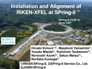
Installation and Alignment of RIKEN-XFEL at SPring-8. SPring-8 (1436 m) since 1997. XFEL (700 m) From 2011. BL29XUL From 2000. Hiroaki Kimura 1,3 ) , Masafumi Yamashita 2 ) , Yusuke Maeda 2 ) , Yoshifumi Tsukamoto 2 ) , Noriyoshi Azumi 1 ) , Sakuo Matsui 1 ) , Noritaka Kumagai 1 ).

E N D
Installation and Alignment of RIKEN-XFEL at SPring-8 SPring-8 (1436 m) since 1997 XFEL (700 m) From 2011 BL29XUL From 2000 Hiroaki Kimura1,3), Masafumi Yamashita2), Yusuke Maeda2), Yoshifumi Tsukamoto2), Noriyoshi Azumi1), Sakuo Matsui1), Noritaka Kumagai1) 1)RIKEN/SPring-8, 2)SPring-8 Service Co., Ltd. 3)JASRI/SPring-8
Short Period Undulator Lower Beam Energy High Gradient Accelerator Short Accelerator Length 1. Overview of our XFEL 2. Strategy of alignment 3. Vertical direction measurement 4. Horizontal direction measurement 5. Alignment of C-, S- band accelerator Section 6. Summary Outline RIKEN’s XFEL: SPring-8 Compact SASE Source (SCSS) Concept In-Vacuum Undulator : lu= 18 mm, K=1.9, lx < 1 Å E= 8 GeV, 8 GeV, C-band 35 MV/m 230 m Accelerator length of 400 m
Schematic view of XFEL Embankment Weathering bedrock Bedrock Replacement by excavation with crusher stone Concrete pillar Diameter: 1.5 or 1.6m Total :139 Length :19-52m (Ave. 30m) Subsidence ~ 20mm/10years Bedrock or Replacement with crusher stone. Subsidence < 2mm/10years Mar. 2009: Building completed Apr. 2009: Installation started Oct. 2010: Aging of accelerator starts Feb. 2011: Beam commissioning starts 3
Our situations under the alignment work 1. Requested Accuracy of V&H directions Accelerator Sec.: ±0.1mm(BPM, Q-Mag),±0.15mm(Accel. Str.) , Smooth/400m Light Source Sec. :±0.1mm/110m(Undulator Sec.) Final goal : 30μm/110m and5μm/12m at Undulator Section → X-ray Based Alignmentand Beam Based Alignment Girders of Undulators and Q&BPMs are equipped remote positioning system. 2. The period for installation & alignment work is 18 months. 3. Displacement of the floor is not small. ~2mm/year 4. 1 time / 1~2months Survey is needed. → Half week for the entire survey, Compact survey network
Strategy of Alignment ・Reference monuments were mounted at intervals of about 30m as a beam line reference for alignment at 700mm horizontal off-set position. Total: 32, Accel. Tunnel:14, U. Hall for BL3:9 for BL1: 9 ・Accelerator components and stone tables were aligned using a laser tracker, its coordinate system was made from two nearby monuments and an inner level. → Permanent monuments have the advantage that the alignment work is started at once in an arbitrary place and a measurement accuracy improvement. Survey of Monuments Vertical direction: Digital Level Horizontal direction: Survey Network Entirety: Undulator Hall: By total station using only monuments that queues up straight By laser tracker using monuments of BL3, BL1, and additional points on the Wall (Beam direction: Distance Meter) It takes 3 days to survey for all monuments.
Instrumentation ・Laser Tracker: API T3 & OT ・Digital Level:TrimbleDiNi 0.3 ・Total Station: Leica TDA 5005 ・Optical Plummets: Leica NL ・Distance Meter: Kern ME5000 ・ Optical Level: Wild N3, Nikon AS-2 ・ Laser Range Meter: HILTI PD32 ・ Multi-Directional Lasers: TaJIma AL-KYRJ
Monument ・ Accel. Tunnel:14, U. Hall for BL3:9 for BL1: 9 ・ Reference point: Center of 1.5 inch ball on the target plate ・Horizontal position could be moved on the floor by using a plummet. 200m 400m Straight line Straight line Geoid level Height Difference -0.81mm 16μrad Def. Angle @Switching Mag. 20μrad Deflecting angle ~5 μrad ~30m Digital Level Laser Tracker, TDA 5005 Optical level ME5000 Base level line of XFEL FE & Exp. Undulator Sec. Accelerator Sec.
Vertical Direction By Digital Level History of Floor subsidence from Aug. 2008 Accelerator Building Area The shape of the subsidence data is very similar to that of embankment. It is as same as the case of BL29XUL(not pillar structure) Recent subsidence 0.15mm/month @ Z= 200m (BL29XUL 8mm/year@BL29XUL ) Light Source Building Area Recent subsidence is small.
Subsidence of top surface of concrete pillar Observed subsidence is agree with that of floor. Embankment Bedrock 9
Vertical Direction By Digital Level History of Floor subsidence from Aug. 2008 Adjusted before installation Difference of Monument from ideal line +1mm +2mm +1mm Reference point Difference of monument position is within 1mm.
Horizontal direction: Survey network Entirety (640m) ・23 control points only monuments that queues up straight. ・4 measuring positions ・ by TS using ATR ・Accuracy of ATR:1” → Estimated error of network: ± 0.5mm Light Source Building (240m) BL3 ID ID ID ID ID ID BL1 Measuring Position Control Point ・ by Laser Tracker ・28 control points ・Monuments for BL3: 9 ・Monumentsfor BL1: 9 ・Additional points on the Wall :10 size: 240m × 8 m ・9 measuring positions ・Accuracy of LT :1”, 20μm+0.2ppm → Estimated error of network: ±0.2mm
Horizontal Direction By Total Station Survey network Difference of Monument from ideal line Light Source Building Accelerator Building North South We defined two fixed points. Building curves, swells with the south. -10 ~ +15 mm /7years@BL29XUL Entirety consists of three straight line.
Displacement at Light Source Building Vertical By Digital Level Undulator-Section Horizontal By LT survey network We defined two fixed points at both side of Und. section. Difference of monument position in Undulator section is within 0.1mm in both directions. 13 Digital level data (res. 10μm) is good agreement with HLS data(res. 0.1μm).
Alignment of Accelerating Structure CCR Fiducials Alignment Unit Using the laser tracker C & S-band accelerator section (~400m) 136 accelerating structures 24 stone tables for Q-magnet and BPM. Adjustment Unit Check of Alignment Using the digital level and the total station 14
Position of Accelerator Components Vertical Difference(mm) C-band S-band Horizontal C-band Difference(mm) Most part is aligned smoothly. ・There are some jump at several parts. 15
Summary Strategy of alignment: We adopted permanent monuments and compact survey network. Displacement of floor: It was within our expectation. → It is important to know the history of the ground displacement for the new facility. We should take care of the displacement of floor in the future Difference of reference monuments from ideal line: At Accelerator building: Vertical: 1mm Horizonta: 2mm At Light Source building: 0.2mm, 0.1mm in ID section Alignment of components: Most component is good. Some smoothing is needed before beam commissioning in next February. Acknowledgements ・IHI Inspection & Instrumentation Co., ltd. ・Pasco Corp., especially Dr. Mishima
Displacement of BL29XUL in 7years @IWAA2008 Vac. Sta.# Level(mm) Top View Side View Alti.(m) 50m Original Altitude Line North :GNSS others:TS Lateral(mm) Vac. Sta.# South Ground displacement depends on that of embankment. → Accelerator section of XFEL building (located at #35 - #64) Level: Subsidence at#51: 54mm (8mm / year) Lateral: Displacement : ~-5 ~ +15mm