Chapter 7: The Software Process
Chapter 7: The Software Process. Prof. Steven A. Demurjian Computer Science & Engineering Department The University of Connecticut 371 Fairfield Road, Box U-2155 Storrs, CT 06269-2155. steve@engr.uconn.edu http://www.engr.uconn.edu/~steve (860) 486 – 4818 (860) 486 – 3719 (office).

Chapter 7: The Software Process
E N D
Presentation Transcript
Chapter 7: The Software Process Prof. Steven A. Demurjian Computer Science & Engineering Department The University of Connecticut 371 Fairfield Road, Box U-2155 Storrs, CT 06269-2155 steve@engr.uconn.edu http://www.engr.uconn.edu/~steve (860) 486 – 4818 (860) 486 – 3719 (office)
Overview of Chapter 7 • Software Production Process Models • Focus on the “How” of Software Development • Stages, Phases, Steps: Methodology • Consider Six Process Models • Waterfall Model • Evolutionary Model • Transformation Model • Spiral Model • UML Unified Process (Slide 85ff – UML Slides) • Agile Software Development • Other Process Issues • Configuration Management • Standards
Software Production Process • Phases and Actions to Build, Deliver, Evolve Product • Objectives • Construct Programs from Idea to Completion • Produce Reliable, Predictable, and Efficient SW • Difficult to Automate • Software Production is a Highly Intellectual Activity • Software is Highly Instable • Interactions of Individuals from Various Backgrounds • Interface to OS, Hardware, Databases, etc. • Production Models Focus on the Software Lifecycle Emphasizing the Process from Start to Finish
Motivation • Increase in Application Complexity and Requirements has Led to Separation Between Developers and Users • Software Now Targets Users without “Computer Expertise” • Higher Level of Quality and Reliability Needed • Software Development as Group Activity • Software Development Needs to: • Manage Complexity in Modern Applications • Provide Detailed Careful Analysis of User Requirements • Boehm States that Goals of a Process Model are: • Determine Appropriate Stages • Establish Transition Criteria for Progressing from One Stage to Another
Completion of All Phases (thru Delivery) Implies a Valid, Verified Product Intended for Traditional Procedural PLs (C, Pascal, Fortran, PL/I, etc.) Multiple Phases for Development Complete One Phase before Next Begins Waterfall Model – Classic Approach Feasibility Study Requirements Analysis and Specification Design and Specification Coding and Module Testing Integration and System Testing Delivery Maintenance
Waterfall Model • First Appeared in late 1950s - Popularized in 1970s • Describes a Sequential Linear Flow Among Phases • Output of one Phase is Input to Next • Many Variants of Waterfall Model • Software Categories Influence Variants of Model • Customized Software for Particular Customer • Customized Software for Company • Generalized Application for Commercial Market • Software Production Companies • Define Outputs for Each Phase • Define Methods to be used to Produce Outputs • Organize Methods into SW Development Methodology • Briefly – Let’s Review Each Phase
Feasibility Study • Purpose: Produce a Feasibility Study Document that Evaluates Cost and Benefits of Application • People: Customer, End User, SW Engineers • Contents Highly Dependent on Application Domain • Feasibility Study Should Contain: • Definition of the Problem • Alternative Solutions and Expected Benefits • Required Resources, Costs, and Delivery Dates • Global Problem Analysis • Decide Future Worth of Software • How Complete can this Document be early in the Development Process?
Requirements Analysis/Specification • Purpose: Identify Required Qualities of Application • People: Interactions Between Users & SW Engineers • States the Required Qualities not How Attained • Produces a Requirements Specification Document • Formal Methods Translated into Natural Language for End Users • Includes User Manual with Screen Mockups • System Test Plan and Strategies/Scenarios • Critical Issues of • Separation of Concerns • Abstraction • Modularity
Requirements Analysis/Specification • Vertical Modularity: Each Module Hides Lower Level Design Decisions • Horizontal Modularity: System is Collection of Views of Some Level of Abstraction – Provide View of • Model of Data (ER or other Diagram) • Model of Functions (DFD, SC, AD, etc.) • Model of Control (Petri Nets, FSM, etc.) • Requirements Specification Document Contains • Functional Requirements – what Product Does • Non-Functional Requirements • Reliability (Available, Secure, Integrity, Safety, …) • Accuracy of Results, Performance, HCI • Operating/Physical Constraints, Portability, …
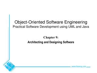
Design and Specification • Purpose: Decompose System into Modules • People: SW Engineers and Managers • Produces a Design Specification Document Containing a Description of Software Architecture • Decomposition usually has Two Phases: • Preliminary Design • Detailed Design • Design Specifications Document Must Follow a Company’s Standard • Design Alternatives Proposed and Evaluated • Multiple Ways to Solve Problem • Paper Methods (Simulation, Queueing, etc.) • Evaluate w.r.t. Requirements Analysis/Spec
Coding and Module Testing • Purpose: Actually Code and Test Software • People: SW Engineers and Managers, End Users (test) • Programming-in-the Small • Alternatives Implemented and Evaluated • List vs. Array vs. API (Set, Collection, …) • Different Algorithms w.r.t. Space and/or Time • Usage of Company Wide Standards • Program Layout, Comments and Headers, Naming Conventions • Module Testing (WBT, BBT) also via Standards • Other Activities Include • Code Inspection for Adherence to Standards • Check for Software Qualities (Performance)
Integration and System Testing • Purpose: Assemble Application from Individual Components and Test • People: SW Engineers, Teams, Managers, Users • Programming-in-the Large • Collections of Modules and Entire System Tested • Incremental Testing • Big-Bang Testing • Alpha Testing – Test Under Realistic Conditions with “Understanding” or “Forgiving” Users • Usage of Company Wide Standards • Method of Integration • Test Data Design • Documentation of Tests and Results
Delivery and Maintenance • Purpose: Application Distributed to Users and Supported via Maintenance/Evolution (A, C, and P) • People: Shipping Personnel, SWE, End Users • Two Stage Deliver • Beta Testing – Selective Group of Expected Users to Shake out all Bugs • Product Delivered to Customers • Leintz and Swanson’s Study Found: • Changes to User Requirements 42% • Changes in Data Format 17% • Emergency Fixes 12% Routine Debugging 9% • Hardware Changes 6% • Documentation Improvements 5% • Efficiency Improvements 4%
Other Activities in Waterfall Model • Documentation • Waterfall Model is Document Driven • Output of Phases is Documented • Company Standards Dictate Document Format • Verification • Emphasized During Module and System Testing • Appropriate Verification Occurs via Reviews, Walk-Throughs, Code Inspection • Goal – Monitor Application Quality Throughout Development Process – Discover/Remove Errors • Management • Tailor the Process to Fit the Product • Configuration and Version Management • Human Resources (Personnel and Organization)
Waterfall Model - Evaluation • Contributions to Understanding Software Processes • Software Development Must be Disciplined, Planned, and Managed • Implementation Delayed Until Objectives Clearly Understood • Characteristics of Waterfall Model • Linear: From Beginning to End w/o Backtracking • Rigidity: • Results of Each Phase Completed Before Proceeding to Next Phase • Assumes Requirements and Specs Finalized • Monolithic: All Planning is Oriented to Single Delivery Date • What are the Problems with this Process?
Waterfall Model - Evaluation • Problems with Waterfall Model • Forces Cost Estimation and Project Planning to Occur After Limited Analysis Performed • Verification of Requirements Spec Document Performed by Customer Not Very Effective • Unrealistic to Assume all Requirements Frozen before Development Starts • User’s Often Don’t Know Exact Requirements • Particularly Early in the Process • Does not Stress Anticipating Changes • Enforces Standards Based on Producing Particular Documents at Specific Times
Waterfall Process Model with Feedback Requirements Analysis and Specification Design and Specification Coding and Module Testing 50 % TIME & COST Integration and System Testing Delivery and Maintenance 50 %
Evolutionary Model • F. Brooks Advocates Producing a Product Twice • First Version is Throwaway to Provide Means for Users to Offer Feedback on Exact Requirements • Second Version Developed using Waterfall • Evolutionary or Incremental Approach • Emphasizes Stepwise Development • Flexible and Non-Monolithic • Postpones Parts of Some Stages • Several Different Variants of Evolutionary Model
Evolutionary Process Model Variant • Boehm: “Model Whose stages Consist of Expanding Increments of an Operational Software product, with the Direction of Evolution being Determined by Operational Experience” • Delivered Increment: Self-Contained Functional Unit that is Useful to the Customer • Includes Supporting Material (Doc, Test Plans, Training Materials, etc.) • Development Strategy • Deliver Something to the Real User • Measure Added Value to user • Adjust Design and Objectives Accordingly • Must Use Waterfall Process Discipline • Use Increments to Evolve toward Desired Product
Incremental Implementation Model Variant • Waterfall Model Used until Implementation Phase • Implementation Done Incrementally • Requires Analysis and Design Emphasis on Useful, Deliverable Subsets/Flexible Interfaces • Different Plans are Implemented, Tested, and Delivered at Different Times • Incremental Implementation is only a Partial Solution • May be Missing Functional (Buttons Don’t Work) • May Simulate Portions (Canned Info instead of DB) • What are Advantages? Disadvantages?
Incremental Development & Delivery Model • Incremental Approach Applied to All Waterfall Phases • Achieves Finer Granularity in the Process • Waterfall Model Followed for Different Portions • Increments Developed After user Feedback • Users can Understand What they Actually Need • All Evolutionary Approaches • Incorporate Maintenance into Every Stage of the Model • Employ Evolutionary Prototype that is Progressively transformed into Final Application • Prototyping Helps SWEs Understand User Needs • Requires Tools such as Visio, Rapid GUI tools, etc.
Assessing Evolutionary Models • Problems: • Large Time Gap Between Requirements Specification and Delivery • Emphasis on User Interface and Not Product • May Miss Functional Requirement • May Underestimate DB Complexity/Interactions • Requires Tools to Manage Process (Doable Today) • Advantages: • Product May Closely Follow User Requirements • Supports Anticipation of Change • More Flexible Than Just Waterfall Approach
Transformation Model • Roots in Formal Specification that Views SW D & D as Steps to Transform Spec to Implementation • Internal Requirements are Analyzed and Formally Specified • Formal Specification Transformed into Detailed, Less Abstract Formal Description • Repeat Step 2 Until Description is Executable by Some Abstract Processor • Further Transformations may be Needed to Increase Efficiency • Transformations may be Performed manually by SWE or by Automated Support System
Transformation Model • Two Main Stages • Requirements Analysis for Formal Requirements • Optimization for Performance Tuning • Transformation Controlled by Software Engineering • Take Advantage of Reusable Components • Verify Against user Expectations • Supported by Software D&D Environment • Tools for Requirements Verification, Managing Reusable Components, Optimizing, Config. Mgmt. • Transformation Model Studied for Small Programs to Mathematically Prove Correctness • Idea of an Automated Assistant to Watch Over the Shoulder of Software Engineers • Isn’t this What Today’s SDEs/IDEs Provide?
Spiral Model • Purpose: Provide a Framework for Design Production Process Guided by Risk Levels • Guiding Principles: Level of Risk (Potential Adverse Circumstance) • Risk Management (Boehm): “Discipline whose objectives are to identify, address, and eliminate software risk items before they become either threats to successful software operation or a major source of expensive software rework.” • Focus on Identifying and Eliminating High Risk Problems by Careful Process Design/Assessment
Spiral Model • Cyclical Model is Four Stages: • Identify Objectives and Design Alternatives • Evaluate Alternatives and Identify/Deal with Potential Risks • Develop and Verify Next Level Product • Review Results and Plan for Next Iteration • Allows Unstated Requirements to Become Part of Specification of Next Cycle • Robustness Approximates Correctness More Closely
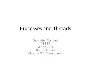
UML Unified Process • UML as a Model Can’t Work in Isolation • Large Scale System Design/Development Involves • Team-Oriented Efforts • Software Architectural Design • System Design, Implementation, Integration • The Unified Process by Rational is • Iterative and Incremental • Use Case Driven • Architecture-Centric
Creating the Unified Process Rational Unified Process 5.0 Functional testing Performance testing Requirements mgmt Conf. and change mgmt Business engineering Data engineering UI design 1998 Rational Objectory Process 4.1 1996-1997 UML Rational Approach Objectory Process 1.0-3.8 1987-1995 Ericsson Approach
What Is a Process? • Defines Whois doing What, When to do it, and How to reach a certain goal. New or changed system New or changed requirements Software Engineering Process
Lifecycle Phases Inception Elaboration Construction Transition time • Inception Define the scope of the project /develop business case • Elaboration Plan project, specify features, and baseline the architecture • Construction Build the product • Transition Transition the product to its users
Unified ProcessIterations and Workflow Phases Process Workflows Inception Elaboration Construction Transition Business Modeling Requirements Analysis & Design Implementation Test Deployment Supporting Workflows Configuration Mgmt Management Environment Preliminary Iteration(s) Iter.#1 Iter.#2 Iter.#n Iter.#n+1 Iter.#n+2 Iter.#m Iter.#m+1 Iterations
Workflows and Models Use Case Model Analysis Model Design Model Impl. Model Test Model UML diagrams provide views into each model Requirements Analysis Deploym. Design Model Implementation Test Each workflow is associated with one or more models.
Use Case Model Use Case Model Analysis Model Design Depl. Model Model Impl. Model Test Model Use Case Diagrams Class Diagrams Object Diagrams Component Diagrams Deployment Diagrams Sequence Diagrams Collaboration Diagrams Statechart Diagrams Activity Diagrams
Analysis & Design Model Use Case Model Analysis Model Design Depl. Model Model Impl. Model Test Model Use Case Diagrams Class Diagrams Object Diagrams Component Diagrams Incl. subsystems and packages Deployment Diagrams Sequence Diagrams Collaboration Diagrams Statechart Diagrams Activity Diagrams
Deployment and Implementation Model Use Case Model Analysis Model Design Depl. Model Model Impl. Model Test Model Use Case Diagrams Class Diagrams Object Diagrams Component Diagrams Deployment Diagrams Incl. active classes and components Sequence Diagrams Collaboration Diagrams Statechart Diagrams Activity Diagrams
Test Model Use Case Model Analysis Model Design Depl. Model Model Impl. Model Test Model Use Case Diagrams Class Diagrams Object Diagrams Component Diagrams Deployment Diagrams Test model refers to all other models and uses corresponding diagrams Sequence Diagrams Collaboration Diagrams Statechart Diagrams Activity Diagrams
Use Case Driven Analysis Reqmt.’s Design Impl. Test Use Cases (scenarios) bind these workflows together
Use Cases Drive Iterations • Drive a Number of Development Activities • Creation and Validation of the System’s Architecture • Definition of Test Cases and Procedures • Planning of Iterations • Creation of User Documentation • Deployment of System • Synchronize the Content of Different Models
Architecture-Centric Inception Elaboration Construction Transition time Architecture • Models Are Vehicles for Visualizing, Specifying, Constructing, and Documenting Architecture • The Unified Process Prescribes the Successive Refinement of an Executable Architecture
Architecture and Models Use Case Model Analysis Model Design Model Impl. Model Test Model Deploym. Model Models Views • Architecture embodies a collection of views of the models
Logical Application Architecture Graphical User Interface Graphical User Interface Graphical User Interface Business Object Model Relational Database Business Object Model Relational Database Relational Database
Physical Application Architecture Thinner client, thicker server Client B Client A Client C Application Application WWW Browser CORBA Beans Business Object Services DCOM ADO/R Business Object Engine Web Server HTML CGI ASP Java Beans ETS COM MTS Business Object Server Business Object Services Business Object Services Business Object Engine Business Object Engine Relational Database Server(s)
Complex Internet System Dynamic HTML, JavaScript, Java plug-ins, source code enhancements Client Java, C, C++, JavaScript, CGI Server Java, C, C++, JavaBeans, CORBA, DCOM Application Server Fulfillment System Financial System Inventory System RDBMS Server Nativelanguages
Function versus Form Use cases Architecture • Use Case Specify Function; Architecture Specifies Form • Use Cases and Architecture Must Be Balanced
The Unified Process is Engineered A unit of work A role played by an individual or a team Activity Worker Describe a Use Case Analyst responsible for Artifact A piece of information that is produced, modified, or used by a process Use case Use case package
Agile Development Jump to Other Presentation