
DESIGNING A TEMPERATURE SENSOR
E N D
Presentation Transcript
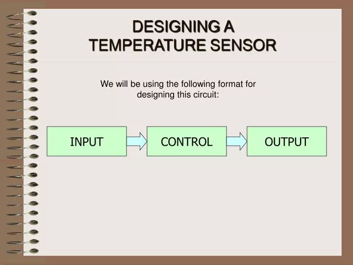
DESIGNING A TEMPERATURESENSOR We will be using the following format for designing this circuit: INPUT CONTROL OUTPUT
Firstly we need a THERMISTOR. This alters its RESISTANCE according to temperature. As it heats up, its resistance lowers. This is type has a NEGATIVE TEMPERATURE COEFFICIENT, (NTC), -tº The type used here has a resistance of 5Kohms at 25ºC Symbol CREATING THE INPUT INPUT CONTROL OUTPUT The input is the part that senses temperature and converts it to a voltage.
CREATING THE INPUT INPUT CONTROL OUTPUT We want a VOLTAGE to represent the temperature, but the sensor only changes RESISTANCE. So we add another resistor to form a POTENTIAL DIVIDER.
+9V Voltage Output 0V CREATING THE INPUT INPUT CONTROL OUTPUT When this POTENTIAL DIVIDER is connected across the supply, the output produces a voltage proportional to the temperature. The hotter it gets, the higher the voltage.
CREATING THE CONTROL INPUT CONTROL OUTPUT The voltage from the input changes only a small amount so we need to use a device that is very sensitive to changes in input. An OPERATIONAL AMPLIFIER is an ideal choice. One type designed specifically for this application is known as a COMPARATOR. IC number: LM311
+V supply Vin+ Output Vin- -V supply CREATING THE CONTROL INPUT CONTROL OUTPUT The connections for the COMPARATOR are shown below: A basic rule on how a COMPARATOR operates is: If Vin+ > Vin- then the output is ON So if we connect the signal from the sensor to Vin+, we can connect a voltage to Vin- as a comparison.
CREATING THE CONTROL INPUT CONTROL OUTPUT Remember: If Vin+ > Vin- then the output is ON To produce the REFERENCE voltage to compare against, we need another POTENTIAL DIVIDER. The one shown has had a POTENTIOMETER (variable resistor) added to provide an adjustable output: The range is about to 0.75v to 8.25v Reference Voltage
CREATING THE CONTROL INPUT CONTROL OUTPUT Here is what we have so far with the inputs connected to the COMPARATOR R5 has been added to provide some HYSTERISIS. This means it has slightly different switch-on and switch-off points – it prevents CHATTERING!
CREATING THE OUTPUT INPUT CONTROL OUTPUT We want to switch on a relay when the circuit activates, but the output from the COMPARATOR is not powerful enough. We need a DRIVER. The most basic one is a TRANSISTOR driver. We need around 150mA for a relay. A BC337 can deliver around 500mA so this will be suitable. Collector Base Emitter
CREATING THE OUTPUT INPUT CONTROL OUTPUT The transistor needs a couple of additional components to protect it. The resistor R6 restricts the current flow into the transistor protecting it from damage. Notice the addition of diode D1, this is to prevent damage caused by high EMF voltages generated in the coil.
INPUT CONTROL OUTPUT PUTTING IT ALL TOGETHER INPUT CONTROL OUTPUT This is what we have so far.
PUTTING IT ALL TOGETHER INPUT CONTROL OUTPUT So connecting them all together produces:
PUTTING IT ALL TOGETHER INPUT CONTROL OUTPUT The voltage supply needs to be DECOUPLED. This means putting a capacitor across the supply to smooth it and improve circuit performance.
COMPLETED CIRCUIT INPUT CONTROL OUTPUT The circuit is now complete, showing the switched output connections from the relay. Try this on Crocodile Clips or LiveWire.