Heat Treatment
R. Manna Assistant Professor Centre of Advanced Study Department of Metallurgical Engineering Institute of Technology Banaras Hindu University Varanasi-221 005, India rmanna.met@itbhu.ac.in Tata Steel-TRAERF Faculty Fellowship Visiting Scholar

Heat Treatment
E N D
Presentation Transcript
R. Manna Assistant Professor Centre of Advanced Study Department of Metallurgical Engineering Institute of Technology Banaras Hindu University Varanasi-221 005, India rmanna.met@itbhu.ac.in Tata Steel-TRAERF Faculty Fellowship Visiting Scholar Department of Materials Science and Metallurgy University of Cambridge Pembroke Street, Cambridge, CB2 3QZrm659@cam.ac.uk Heat Treatment
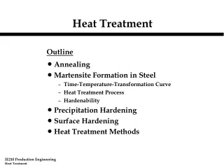
HEAT TREATMENT Fundamentals Fe-C equilibrium diagram. Isothermal and continuous cooling transformation diagrams for plain carbon and alloy steels. Microstructure and mechanical properties of pearlite, bainite and martensite. Austenitic grain size. Hardenability, its measurement and control. Processes Annealing, normalising and hardening of steels, quenching media, tempering. Homogenisation. Dimensional and compositional changes during heat treatment. Residual stresses and decarburisation.
Surface Hardening Case carburising, nitriding, carbonitriding, induction and flame hardening processes. Special Grade Steels Stainless steels, high speed tool steels, maraging steels, high strength low alloy steels. Cast irons White, gray and spheroidal graphitic cast irons Nonferrous Metals Annealing of cold worked metals. Recovery, recrystallisation and grain growth. Heat treatment of aluminum, copper, magnesium, titanium and nickel alloys. Temper designations for aluminum and magnesium alloys. Controlled Atmospheres Oxidizing, reducing and neutral atmospheres.
Suggested Reading R. E. Reed-Hill and R. Abbaschian: Physical Metallurgy Principles, PWS , Publishing Company, Boston, Third Edition. Vijendra Singh: Heat treatment of Metals, Standard Publishers Distributors, Delhi. Anil Kumar Sinha: Physical Metallurgy Handbook, McGraw-Hill Publication. H. K. D. H. Bhadeshia and R. W. K. Honeycombe: Steels-Microstructure and Properties, Butterworth-Heinemann, Third Edition, 2006 R. C. Sharma: Principles of Heat Treatment of Steels, New Age International (P) Ltd. Publisher. Charlie R. Brooks: Heat Treatment: Structure and Properties of Nonferrous Alloys, A. S. M. Publication.
Definition of heat treatment Heat treatment is an operation or combination of operations involving heating at a specific rate, soaking at a temperature for a period of time and cooling at some specified rate. The aim is to obtain a desired microstructure to achieve certain predetermined properties (physical, mechanical, magnetic or electrical).
Objectives of heat treatment (heat treatment processes) The major objectives are • to increase strength, harness and wear resistance (bulk hardening, surface hardening) • to increase ductility and softness (tempering, recrystallization annealing) • to increase toughness (tempering, recrystallization annealing) • to obtain fine grain size (recrystallization annealing, full annealing, normalising) • to remove internal stresses induced by differential deformation by cold working, non-uniform cooling from high temperature during casting and welding (stress relief annealing)
to improve machineability (full annealing and normalising) • to improve cutting properties of tool steels (hardening and tempering) • to improve surface properties (surface hardening, corrosion resistance-stabilising treatment and high temperature resistance-precipitation hardening, surface treatment) • to improve electrical properties (recrystallization, tempering, age hardening) • to improve magnetic properties (hardening, phase transformation)
Fe-cementite metastable phase diagram (Fig.1) consists of phases liquid iron(L), δ-ferrite, γ or austenite, α-ferrite and Fe3C or cementite and phase mixture of pearlite (interpenetrating bi-crystals of α ferrite and cementite)(P) and ledeburite (mixture of austenite and cementite)(LB). Solid phases/phase mixtures are described here.
Fig.1: Fe-Cementite metastable phase diagram (microstructural) L=liquid, Cm=cementite, LB=ledeburite, δ=delta ferrite, α= alpha ferrite, α’= alpha ferrite(0.00005 wt%C) γ=austenite, P=pearlite, eu=eutectic, ed=eutectoid, I=primary, II=secondary, III=tertiary δ+L L 1539˚C δ A5=1495˚C 0.09 0.53 Weight percent carbon δ+γ 0.17 1227˚C L+γI 1394˚C 4.30 L+CmI γ γI+LB LB+CmI A4=1147˚C 2.11 LB’ (γeu(γII +CmII)+Cmeu) +CmI γI’(γII+CmII)+LB’ (γ’eu(γII +CmII)+Cmeu) A B C Temperature, °C Acm 910˚C D E F A2 =668/ 770˚C A3 Cm Ledeburite=LB(γeu+Ceu) 0.77 αI+γ γII+CmII 0.0218 A1=727˚C α P(αed+Cmed) +CmII (P(αed+Cmed)+CmII)+ LB’ (P(αed+Cmed) +CmII+Cmeu) LB’ (P(αed+Cmed) +CmII)+Cmeu)+CmI Pearlite αI+ (P(αed +Cmed) αI(α’+CmIII)+(P(αed(α’ed+CmIII)+Cmed) P(αed (α’ed +CmIII)+Cmed) +CmII (P(αed(α’ed+CmIII)+Cmed) +CmII)+ LB’ ((P(αed(α’ed+CmIII)+Cmed) +CmII)+Cmeu) LB’ ((P(αed(α’ed+CmIII)+Cmed) +CmII)+ Cmeu)+CmI Ao=210˚C α’+CmIII 6.67 0.00005
δ ferrite: Interstitial solid solution of carbon in iron of body centred cubic crystal structure (Fig .2(a)) (δ iron ) of higher lattice parameter (2.89Å) having solubility limit of 0.09 wt% at 1495°C with respect to austenite. The stability of the phase ranges between 1394-1539°C. Fig.2(a): Crystal structure of ferrite This is not stable at room temperature in plain carbon steel. However it can be present at room temperature in alloy steel specially duplex stainless steel.
γ phase or austenite: Interstitial solid solution of carbon in iron of face centred cubic crystal structure (Fig.3(a)) having solubility limit of 2.11 wt% at 1147°C with respect to cementite. The stability of the phase ranges between 727-1495°C and solubility ranges 0-0.77 wt%C with respect to alpha ferrite and 0.77-2.11 wt% C with respect to cementite, at 0 wt%C the stability ranges from 910-1394°C. Fig.3(a ): Crystal structure of austenite is shown at right side.
Fig. 3(b): Polished sample held at austenitisation temperature. Grooves develop at the prior austenite grain boundaries due to the balancing of surface tensions at grain junctions with the free surface. Micrograph courtesy of Saurabh Chatterjee.
α-ferrite: Interstitial solid solution of carbon in iron of body centred cubic crystal structure (α iron )(same as Fig. 2(a)) having solubility limit of 0.0218 wt % C at 727°C with respect to austenite. The stability of the phase ranges between low temperatures to 910°C, and solubility ranges 0.00005 wt % C at room temperature to 0.0218 wt%C at 727°C with respect to cementite. There are two morphologies can be observed under equilibrium transformation or in low under undercooling condition in low carbon plain carbon steels. These are intergranular allotriomorphs (α)(Fig. 4-7) or intragranular idiomorphs(αI) (Fig. 4, Fig. 8)
Fig. 4: Schematic diagram of grain boundary allotriomoph ferrite, and intragranular idiomorph ferrite.
Fig.5: An allotriomorph of ferrite in a sample which is partially transformed into α and then quenched so that the remaining γ undergoes martensitic transformation. The allotriomorph grows rapidly along the austenite grain boundary (which is an easy diffusion path) but thickens more slowly.
Fig.6: Allotriomorphic ferrite in a Fe-0.4C steel which is slowly cooled; the remaining dark-etching microstructure is fine pearlite. Note that although some α-particles might be identified as idiomorphs, they could represent sections of allotriomorphs. Micrograph courtesy of the DOITPOMS project.
Fig.7: The allotriomorphs have in this slowly cooled low-carbon steel have consumed most of the austenite before the remainder transforms into a small amount of pearlite. Micrograph courtesy of the DoITPOMS project. The shape of the ferrite is now determined by the impingement of particles which grow from different nucleation sites.
Fig. 8: An idiomorph of ferrite in a sample which is partially transformed into α and then quenched so that the remaining γ undergoes martensitic transformation. The idiomorph is crystallographically facetted.
There are three more allotropes for pure iron that form under different conditions ε-iron: The iron having hexagonal close packed structure. This forms at extreme pressure,110 kbars and 490°C. It exists at the centre of the Earth in solid state at around 6000°C and 3 million atmosphere pressure. FCT iron: This is face centred tetragonal iron. This is coherently deposited iron grown as thin film on a {100} plane of copper substrate Trigonal iron: Growing iron on misfiting {111} surface of a face centred cubic copper substrate.
Fe3C or cementite: Interstitial intermetallic compound of C & Fe with a carbon content of 6.67 wt% and orthorhombic structure consisting of 12 iron atoms and 4 carbon atoms in the unit cell. Stability of the phase ranges from low temperatures to 1227°C Fig.9(a): Orthorhombic crystal structure of cementite. The purple atoms represent carbon. Each carbon atom is surronded by eight iron atoms. Each iron atom is connected to three carbon atoms.
Fig.9(b): The pearlite is resolved in some regions where the sectioning plane makes a glancing angle to the lamellae. The lediburite eutectic is highlighted by the arrows. At high temperatures this is a mixture of austenite and cementite formed from liquid. The austenite subsequently decomposes to pearlite. Courtesy of Ben Dennis-Smither, Frank Clarke and Mohamed Sherif
Critical temperatures: A=arret means arrest A0= a subcritical temperature (<A1) = Curie temperature of cementite=210°C A1=Lower critical temperature=eutectoid temperature=727°C A2=Curie temperature of ferrite=768/770°C A3=upper critical temperature=γ+α /γ phase field boundary =composition dependent=910-727°C A4=Eutectic temperature=1147°C A5=Peritectic temperature=1495°C
Acm=γ/γ+cementite phase field boundary=composition dependent =727-1147°C In addition the subscripts c or r are used to indicate that the temperature is measured during heating or cooling respectively. c=chaffauge means heating, Ac r=refroidissement means cooling, Ar Types/morphologies of phases in Fe-Fe3C system Cementite=primary (CmI), eutectic (Cmeu), secondary (CmII)(grain boundary allotriomophs, idiomorphs), eutectoid (Cmed) and tertiary(CmIII). Austenite= austenite(γ)(equiaxed), primary (γI), eutectic (γeu), secondary (γII) (proeutectoid), α-ferrite=ferrite (α) (equiaxed), proeutectoid or primary (grain boundary allotriomorphs and idiomorphs)(αI), eutectoid(αeu) and ferrite (lean in carbon) (α’). Phase mixtures Pearlite (P) and ledeburite(LB)
Important Reactions Peritectic reaction Liquid+Solid1↔Solid2 L(0.53wt%C)+δ(0.09wt%C)↔γ(0.17wt%C) at 1495°C Liquid-18.18wt% +δ-ferrite 81.82 wt%→100 wt% γ Fig.10:δ-ferrite in dendrite form in as-cast Fe-0.4C-2Mn-0.5Si-2 Al0.5Cu, Coutesy of S. Chaterjee et al. M. Muruganath, H. K. D. H. Bhadeshia
Eutectic reaction Liquid↔Solid1+Solid2 Liquid (4.3wt%C) ↔ γ(2.11wt%C) + Fe3C (6.67wt%C) at 1147˚C Liquid-100 wt% →51.97wt% γ +Fe3C (48.11wt%) The phase mixture of austenite and cementite formed at eutectic temperature is called ledeburite. Fig.11: Microstructure of white cast iron containing massive cementite (white) and pearlite etched with 4% nital, 100x. After Mrs. Janina Radzikowska, Foundry Research lnstitute in Kraków, Poland
Fig. 12: High magnification view (400x) of the white cast iron specimen shown in Fig. 11, etched with 4% nital. After Mrs. Janina Radzikowska, Foundry Research lnstitute in Kraków, Poland
Fig. 13: High magnification view (400x) of the white cast iron specimen shown in Fig. 11, etched with alkaline sodium picrate. After Mrs. Janina Radzikowska, Foundry Research lnstitute in Kraków, Poland
Eutectoid reaction Solid1↔Solid2+Solid3 γ(0.77wt%C) ↔ α(0.0218wt%C) + Fe3C(6.67wt%C) at 727°C γ (100 wt%) →α(89 wt% ) +Fe3C(11wt%) Typical density α ferrite=7.87 gcm-3 Fe3C=7.7 gcm-3 volume ratio of α- ferrite:Fe3C=7.9:1
Fig. 14: The process by which a colony of pearlite evolves in a hypoeutectoid steel.
Fig. 15 : The appearance of a pearlitic microstructure under optical microscope.
Fig. 16: A cabbage filled with water analogy of the three-dimensional structure of a single colony of pearlite, an interpenetrating bi-crystal of ferrite and cementite.
Fig. 17: Optical micrograph showing colonies of pearlite . Courtesy of S. S. Babu.
Fig. 18: Transmission electron micrograph of extremely fine pearlite.
Fig.19: Optical micrograph of extremely fine pearlite from the same sample as used to create Fig. 18. The individual lamellae cannot now be resolved.
Evolution of microstructure (equilibrium cooling) Sequence of evolution of microstructure can be described by the projected cooling on compositions A, B, C, D, E, F. At composition A L δ+L δδ+γγγ+αI αα’+CmIII At composition B L δ+L L+γIγαI +γ αI+ (P(αed+Cmed) αI(α’+CmIII)+(P(αed(α’ed+CmIII)+Cmed)
L+γI γII+CmII P(αed+Cmed)+CmII P(αed (α’ed+CmIII)+Cmed)+CmII At composition C L γ At composition D L L+γI γI+LB γI’(γII+CmII)+LB’ (γ’eu(γII+CmII)+Cmeu) (P(αed+Cmed)+CmII)+ LB’ (P(αed+Cmed)+CmII+Cmeu) (P(αed(α’ed+CmIII)+Cmed) +CmII)+ LB’ ((P(αed(α’ed+CmIII)+Cmed)+CmII)+Cmeu)
L+CmI LB(γeu+Cmeu+CmI LB’ (γeu(γII+CmII)+Cmeu)+CmI At composition E L At composition F L Fe3C LB’ (P(αed+Cmed)+CmII)+Cmeu)+CmI LB’ ((P(αed(α’ed+CmIII)+Cmed) +CmII)+ Cmeu)+CmI
Limitations of equilibrium phase diagram Fe-Fe3C equilibrium/metastable phase diagram Stability of the phases under equilibrium condition only. It does not give any information about other metastable phases. i.e. bainite, martensite It does not indicate the possibilities of suppression of proeutectoid phase separation. No information about kinetics No information about size No information on properties.