Download
1 / 164
2.37k likes | 3.43k Vues
RF & Microwave Fundamentals. Jan 2006 Anritsu Korea. • Definition of Terms • What Does RF Mean? • Basic Concepts • Transmission Lines • Coaxial Cable • Waveguide • Transmission Line Theory • Transmission measurements and error analysis.

E N D
RF & Microwave Fundamentals Jan 2006 Anritsu Korea
• Definition of Terms • What Does RF Mean? •Basic Concepts • Transmission Lines •Coaxial Cable •Waveguide • Transmission Line Theory • Transmission measurements and error analysis •Return Loss measurements and error analysis •Advanced Measurement Techniques (air lines) •S Parameters & VNA measurement fundamentals •Common Microwave Devices and measurements •Synthesizer related RF Concepts Basic Fudamentals
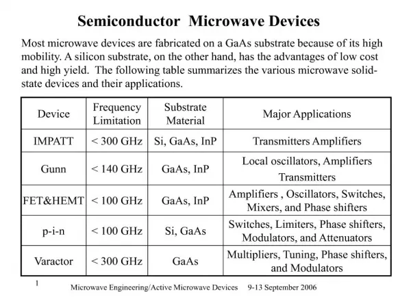
Electromagnetic Spectrum • RF Radio Frequency. A general term used to describe the frequency range from 3 kHz to 3.0 GHz (Gigahertz ) • Microwave. The frequency range 3GHz to 30.0 GHz. Above 1 GHz, lumped circuit elements are replaced by distributed circuit elements. • Millimeter wave. The frequency range 30 GHz to 300 GHz. The corresponding wavelength is less than a centimeter.
Range of RF Frequencies • Medium Frequency (300 KHz - 3 MHz) • High Frequency (HF) (3 - 30 MHz) • Very High Frequency (VHF) (30 - 300 MHz) • Ultra High Frequency (UHF) (300 - 3000 MHz)
Some Terms You Will Hear • dB • dBm • Impedance • Return Loss (RL) • Insertion Loss (Cable Loss) • VSWR • DTF • Watts
Linear vs Log • Some things are very, very large. • Some things are very, very small. It is difficult to express comparison of sizes in common units of measure with a linear scale. One would not usually express a flea’s dimensions in miles, for example.
Bel • A bel is defined as the logarithm of a power ratio. Po bel = log Pi
Decibel (dB) • Decibel (dB) is a logarithmic unit of relative power measurement that expresses the ratio of two power levels. Po dB = 10 log Pi
dBm • dBm is the decibel value of a signal compared to 1 m w.
3 dB rule • +3 dB means double the power (multiply by 2) • - 3 dB means halve the power (divide by 2)
Power Conversion Table • Some common decibel values and power-ratio equivalents.
Basic Concept Wavelength () Length
Wavelength () VC () = εr f Where: VC = velocity of propagation through air εr = relative dielectric constant f = frequency of oscillation
Velocity of Propagation • Electromagnetic energy travels at the speed of light.
Transmission Line Theory • Must be applied when line lengths are >(/ 4 ) • Standard lumped-circuit analysis can be applied when the line lengths are <<(/ 4 )
Impedance • The impedance of a transmission line can be complex Z = R ± jX If X is positive, it is called the inductive reactance If X is negative, it is called capacitive reactance Impedance plot in a rectangular coordinate
Different Types Transmission Line • There are many different types of transmission lines and we will talk about three of them. • Coaxial • Waveguide • Microstrip
Waveguide • Waveguide is a hollow, conducting tube, through which microwave frequency energy can be propagated.
Characteristic Impedance of Coax For a lossless line R=G=0
Characteristic Impedance Z0 = (138/ εR) Log (D/d)
Propagation Modes of Coax • Patterns set up by electric and magnetic fields.
Cutoff Frequency • The lowest frequency at which the next higher order mode can propagate is called the cut-off frequency of the next higher order mode.
Velocity of Propagation In free space C = 3x10⁸ m/sec Wavelength = λ = C/f Where f = frequency (Hz) Z
Relative Velocity Constant (k) k = (1/ εR) for Teflon: εR = 2.04 k = (1/ 2.04) = 0.7
Phase of The Signal at One Wavelength The phase of the signal at one wavelength intervals along the line will be in phase. In this instance λ0 is 21 cm at 1 GHz.
Well Matched Transmission Line If Z0 = ZL then P0 = PL No reflection Therefore PL = PI
Poorly Matched Transmission Line If ZL ≠Z0 thenPL ≠ PI Reflection is present Therefore PL = PI - PR
Example Short at the end of the line
SWR Vs Impedance ZL 0, ZL and ZL Z0
VSWR • Voltage Standing Wave Ratio (VSWR) Emax ER + EI • VSWR = = Emin ER - EI ER • G(reflection coefficient) = EI
Reflection Coefficient • Reflection coefficient is the ratio of the reflected signal to the incident signal. ZL - Z0 ER/Ei = = || = ZL + Z0
Mismatch Mismatch is a measure of the efficiency of power transfer to the load. The percentage of the power reflected from the Load. 0 dB return loss or infinite VSWR indicate perfect reflection by the load. Infinite return loss or unity VSWR indicate perfect transmission to the load.
Basic Measurements Transmission Loss/Gain = Pout/Pin Return Loss = Preflected/Pin
Transmission Measurement • Combining Signals
Power Gain • Gain is the ratio of the output power level of an amplifier to the input power level to that amplifier. Po Gain = Pi
Transmission Measurement(Loss/Gain Measurement) • Transmission Power Gain = 20 log (Vo/Vi)
Making a Transmission Measurement • Measure incident power going into the device. • Measure the output power coming out of the device. • The difference in power is transmission loss (or gain).
Measure Incident Power • Using detector directly on the test port.
Transmission Measurement Errors • Calibration Error • Test Port Match • Detector Match • Using Adapters