Download
1 / 65
650 likes | 1.17k Vues
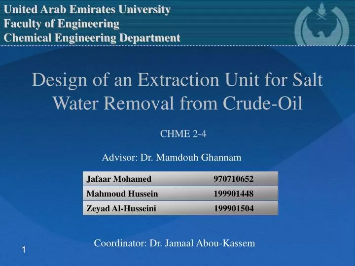
Jafaar Mohamed 970710652. Mahmoud Hussein 199901448. Zeyad Al-Husseini 199901504. United Arab Emirates University Faculty of Engineering Chemical Engineering Department.

E N D
Jafaar Mohamed 970710652 Mahmoud Hussein 199901448 Zeyad Al-Husseini 199901504 United Arab Emirates University Faculty of Engineering Chemical Engineering Department Design of an Extraction Unit for Salt Water Removal from Crude-Oil CHME 2-4 Advisor: Dr. Mamdouh Ghannam Coordinator: Dr. Jamaal Abou-Kassem
Contents • Chemical Treatment. • Point of Application. • Methods of Application. • Chemical feed pumps. • Experiments • Three phase separator Design. • Piping & Instrumentation Diagram. • HAZOP Study. • Indirect Heater Design.. • Environmental Impact.
Continue Content • Experimental Design • Material of Construction. • Cost.
Chemical Treatment • The main idea of this treating is to add some small amounts of surface active emulsion –breaking chemicals (reagents ) into the treated emulsion to deactivate the water in – oil (oil soluble reagent ) • After this treating the free phases separated by gravity exit the vessel
1) Point of Application of Chemicals : • The agitation takes place when the chemicals are sufficient for emulsion breaking . • The chemical injection pump is usually placed at the header of the separator .
2) Relationship of Chemicals to Temperature: In General the increasing of the emulsion’s temperature decreases the amount of chemicals required for its treating
3) Relation of the amount of chemical to settling time • The amount and the type of chemicals define how the emulsion will break out, Sometimes , in chemical treatment , to fasten the break down process of emulsions: 1- Faster – acting chemical can be used 2- The temperature of the emulsion can be increased
Methods of Applying Chemicals • The chemical compounds for chemical treating , usually are put into the produced emulsion at any point in the system . • Depending on the point of the application (injection or adding ) of the compounds there are three basic types of application in chemical treating of oil : • 1- Down hole treating. • 2- Flow line treating. • 3- Batch treating.
1) Down hole treating • Emulsion becomes more viscous when it contains water dispersed in oil by agitation. This makes emulsion resist the flow in the system. • Applying chemical treating down hole breaks the emulsion and makes it easier to lift.
2) Flow line Treating In this treatment the chemical reagent should be injected in flow line at a point where sufficient agitation and treating time are assured, usually this point is at the well head or at the header in multiple well systems.
3) Batch treating • The produced emulsion from the well moves to the treating tank with heaters , where the chemical reagent drips slowly through the holes of a bucket into the emulsion to de-emulsify it. After settling the water will be drain off . • This treating requires more chemical regents.
Demulsifiers • Quality Indexes: are made with the most advanced ethoxylation catalytic polymerization technology developed. • Packing: Packed in 200kg galvanized drum or iron drum. • Storage and Transportation: nonpoisonous and can be dealt with as common chemicals and storage time is one year.
Chemical Feed Pumps • Injecting chemical reagents. • They have adjustable stores • Driven - operated pumps.
DEMULSIFIERS: • ALKAN® DEMULSIFIER • T @ 60o C (140o F) • Combustible • 1 gallon per 20,000 gallons (50 ppm) of oil • 1 gallon per 10,000 gallons (100 ppm) of oil
Demulsification Experiment • Water Concentration 20 vol.%. • Time of mixing 20 min. • 2000 RPM. • Salt conc. 100000 ppm • Demulsifiers conc. (10,25,50,100 ppm) • Plot (volume precipitated vs. Time)
Horizontal Separator Sizing • Sizingparameters: Height Length
Horizontal Separator Sizing • Retention time method. • Drop settling method. • Design consideration.
Horizontal Separator Sizing Basis: • Operating temperature = 60 oC • Operating pressure = 1 atm • Retention time = 5 minutes • Production rate = 50,000 barrel/day
Horizontal vessel design equations • Diameter calculation: (π/4)* D2 *M * Leff = q * tr • Volume calculation: V = C * [(sh1 – sh2) / µw] ) (D/1440) • Length calculation: L = (4/3) * D + Leff
PID Contents 1)All process equipment are identified by an equipment No. 2) All pipes are identified by a line No. (pipe size & material of construction)
3) All control and block valves are identified by numbers. (type & size) 4) Pumps are identified by a code No. 5) All control loops & instrument are with an Identification No.
Types of Valves CV Electronic Butterfly Valve Pneumatic Fails Open Fails Shut
PID Objectives (I) Safe Plant Operation: -To keep process variables within the safe operating limits. -To provide alarms and automatic shut-down system, to detect dangerous situations as they develop. -To provide interlocks and alarms, to prevent dangerous operating procedures.
PID Objectives (II) Production Rate: -To achieve the design product output. (III) Product Quality: -To maintain the product composition within the specified quality standards. (IIV) Cost: -To operate at the lowest production cost.
Hazards and Operability Studies (HAZOP) • Basic Principles • Involves systematic study of the process. • Vessel by vessel • Line by line • Guide words
Guide words • No or Not (No part of the intention is achieved but nothing else happens). • More (Quantitative increase) • Less (Quantitative decrease).
Additional guide words • Intention • Deviation • Causes • Consequences • Hazards
Objective of guide words • Special words are used in a systematic fashion (HAZOP procedure). • To investigate potential hazards and possible solutions.
(I) Intention- emulsion stream transfer from knock out drum to indirect heater
(II) Intention- Outlet stream from indirect heater to the horizontal separator
Indirect Heater • Energy needed to heat the crude Q = • Q = 15 Fo DT (0.5 * r + 0.2) • Q = 11,790,000 Btu/hr • Vessel size • O.D= 96” • L = 30’
Environmental Impact • Burning of fuel gas causes the emission of CO2, H2S..etc to the atmosphere
Indirect Heater Efficiency • Addition of flue gas passes. • Attending to leaks. • Insulating Pipe work and exposed surfaces.