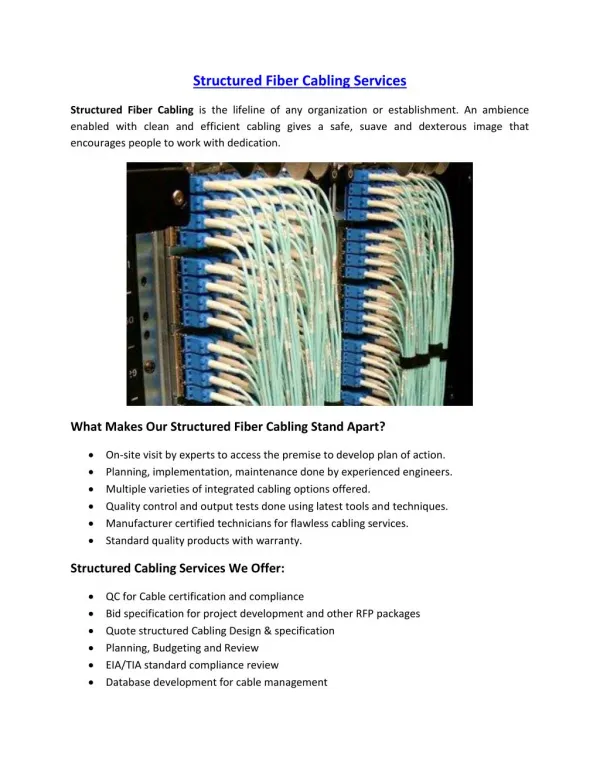
Structured Cabling Project at Honolulu Community College
Join the Cisco Academy Training Center at HCC for Semester 1 Version 2.1.1 Overview focusing on networking media standards, cabling techniques, and equipment found in wiring closets. Learn about RJ45 jacks, labeling standards, and safety precautions.

Structured Cabling Project at Honolulu Community College
E N D
Presentation Transcript
Structured Cabling Project Honolulu Community College Cisco Academy Training Center Semester 1 Version 2.1.1
Overview • Focuses on standards for networking media. • TIA/EIA 568A - cabling standard. • TIA/EIA 606 - labeling standard. • Techniques for dressing and securing the cable. • RJ45 jacks, wiring sequence. • Wiring closet design. • Equipment found in a wiring closet. • patch panels, hubs, bridges, switches, & routers.
TIA/EIA 568A Standards • Defines horizontal cabling.
Telecommunications Outlet • Telecommunications outlets are wall mounted. • TIA/EIA 568A specifies RJ45 jack for making the connection to Cat 5 UTP.
RJ45 Mounting • Two types of wall mounts: • Surface mounting (easier to install, concrete walls) • Adhesive-backed box. • Screw-mounted box. • Flush mounting. • Surface mounting is generally preferred. • Faster, lower labor costs. • Maybe the only option in some cases.
Flush Mounting Concerns • Type of wall material. • Plaster tends to crumble, has wood lath backing. • Wood • more solid support. • Can install in baseboard, but avoid lower 5cm (2”) -need to clear wall’s bottom plate or framing. • Avoid door and window trims. • Drywall - obstructions due to studs every 18-24”. • Check with small hole for obstructions. • Select position 30-45cm (12-18”) above floor. • Level.
Flush Mounting Concerns (cont.) • Safety Precautions • Any time you are working in walls, ceilings, or attics, it is extremely important that you remember to turn off the power to all circuits that go to, or pass through, the work area.
Wires in RJ45 Jack • Performance is closely linked to the quality of the wire connections. • Do not strip off any more of the jacket than needed, about 2.5cm (1”). • Removing too much jacket insulation can slow data throughput. • Arrange wires in proper order. • Keep wires centered in jack. • If skewed, data throughput can decrease. • Use punch tool to “punch down” wires into jack.
Tips in Installing Cable • Strip back cable jacket only as much as needed (about 2.5cm or 1”). • Maintain twists as close as possible to termination (max 13mm (1/2”) for Cat 5 UTP). • Min bend radius is 4 times the diameter of cable; never exceed a 90o bend. • Use cable ties to secure cable, loosely. • Avoid stretching cable, 11.3kg (25 lb) of pull max. • Leave slack in cable, to reach floor and 60-90cm (2-3 ft) in each direction.
Tips in Installing Cable (cont.) • Use Velcro straps; no staples.
Documenting Cable Runs • Documentation is useful when upgrading or modifying the network in the future. • Cut Sheet - diagram of cable runs.
Documentation • TIA/EIA 606 specifies labeling. • Unique identifier required on each termination hardware unit or on label. • Cables are labeled at both ends. • Use unique and descriptive labeling. • Ex. Rm 516 West Wall • Labeling isdesigned to help diagnosis and location of problems. • All labels must meet legibility, defacement, and adhesion requirements (UL969).
Cabling Runs • Run all cables at once, if you need 4 cables, use 4 rolls and pull them all at the same time. • Mark each cable end (3 times). • Tape cables together to pull string. • Label cable ends before cutting the cables.
Routing Cables • Easiest way is to mount cables on wall. • Use tie-wraps to attach cables to walls. • Adhesive tie-wraps - cannot be moved. • Screw mounted tie-wraps - can be moved later.
Raceways • Raceways - wall mounted channels with removable covers. • Two types: • Decorative raceways • finished appearance for use in visible areas. • Gutter • will hold several cables. • Used in attics, dropped ceilings, etc. • Raceways can be adhesive-backed or screw mounted. • Adhesive-backed - easy to install, easy to remove.
Cables in Existing Raceways • Do not run cables next to power lines or in existing raceways with power lines. • Causes EMI (electro-magnetic interference).
Safety Precautions • Turn off power to all circuits in work area. • If unsure, turn off all power. • Know locations of fire extinguishers. • Long pants and sleeves for protection, but avoid baggy clothing. • Survey the area - especially dropped ceiling area. • Wear eye protection. • Be aware of hazards like lead, PCBs or asbestos. • Keep work area orderly and neat.
Building Safety and Codes • Find out local building codes. • Be aware of any restrictions to drilling or cutting holes in fire walls or ceilings. • Holes may need to completely filled with non-combustible patching compounds. • Fire-rated cable must be used in spaces where air is circulated.
Horizontal Cabling Supports • In dropped ceilings, do not lay cable on top of ceiling. • Use wall mount gutters, tie wraps or ladder racks to support cables.
Other Tools • Telepole • Telescoping pole used to string cables. • Fish Tape • Used to run cables thru a wall. • Remember to leave extra cable in the walls and ceilings!
What is a Wiring Closet? • Wiring closet serves as a central junction point for the wiring and wiring equipment used to connect devices in a local area network (LAN). • Center point of star. • Typical equipment: • Patch panels • Hubs • Bridges • Switches • Routers.
MDFs and IDFs • Networks can have several wiring closets (extended star topology). • One is designated as the MDF, main distribution facility. • Other wiring closets are the IDFs, intermediate distribution facilities. • IDFs are connected to the MDF, and are dependent on it. • IDFs connect to MDF by backbone cabling.
Horizontal Cabling Connections • Horizontal cabling usually terminates at the patch panel.
Patch Panels • Provides pin locations and ports. • Pin locations on back (wires are punched down). • Ports (RJ45) on the front of panel. • Wires are color coded, not interchangeable. • Act as switchboard where horizontal cabling from workstation can be connected to other workstations or devices.
Patch Panels (cont.) • Poor connections can cause slower data rates. • Arrange wires in ascending order. • Logical sequence of wires from work area. • Make use of cut sheet. • Keep wires centered in jack. • If skewed, data rate will decrease. • Avoid exposing too much wire (strip off about 38-50 mm (1 1/2” to 2”) of jacket). • Don’t untwist wire pairs more than necessary. • Use punch tool.
Patch Panel Mounting • Most common is distribution rack. • Easy access to front and back. • Need to provide 30-45mm (12” - 18”) in back for physical access. • Standard size of distribution rack is .48m or 19”.
Testing Your Network • 1. Break the system into smaller logical groups or elements. • 2. Test each group or element. • 3. Note any symptoms or problems. • 4. Determine what the most likely problem element is. • 5. Use substitution or additional testing to determine if the likely element is in fact the problem. • 6. If not, proceed to the next most likely element you suspect.
After finding the problem • 7. When the dysfunctional element is found, repair it if possible. • 8. If it is not possible to repair, then replace it.
Network Operations Testing • IEEE & TIA/EIA have established standards to test whether your network is operating at an acceptable level. • use this measurement as baseline. • baseline is a record of your network's starting point or newly installed performance capabilities. • Continue to test your network on a regular basis in order to ensure that it performs at its peak. • Can spot problems that may be caused by aging, poor maintenance practices, weather, etc.
Cable Testers • Cable testers certify cables to IEEE & TIA/EIA standards. • Basic features, can measure: • Cable Distances • Connectivity • Wire maps for crossed pairs. • Split pairs. • Signal Attenuation. • Near-end crosstalk (NEXT). • Noise level tests.
Measuring Distances • Max cable lengths are given by TIA/EIA 568A. • Cable testers use time domain reflectometry to measure the distance to open or shorted end. • TDR sends a signal and times its reflection back from the end of the cable. • Accurate to within 61 cm (2ft).
Connection Tests • Distance measurements can determine whether the connections at the patch panels, or at the telecommunications outlets, are good.
Correct Wiring • Wire map shows which wire pair connections to what pins. • 12 36 45 78 • 12 36 45 78 (Near End) (Far End) Correct Wiring
Crossed Pairs • Crossed pairs are connected in reverse order on one end. • Wire map: 12 36 45 78 21 36 45 78 Correct Wiring Crossed Pair.
Split Pairs • Split pairs occurs when wires used for a circuit are not from the same pair. • Can be detected by visual inspection or by crosstalk measurements. • Split pairs do not have self-shielding. • Cannot be detected by wire map. Split Pairs.
Signal Attenuation • Attenuation is due to loss of energy in the signal (less power). • Cable testers measure signal from a signal injector, attached at far end of the cable. • Attenuation generally measured at several frequencies. • For CAT 5 cable - up to 100 MHz. • TIA/EIA 568A specifies allowable losses in various types of cables.
Near-end Crosstalk • Causes of near-end crosstalk. • Crossed pairs - most common. • Untwisting of wire pairs, usually at patch panel. • Cables too tightly pulled (causing untwisting). • Too sharp corners (bends) - pairs change positions. • Split pairs. • Cable testers measure a series of frequencies up to 100Mhz - higher values are better, low values indicate problem.
Noise Level Test • Sources of Interference: • Fluorescent lights, televisions, monitors, motors, power lines, welders, auto ignitions. • Radio stations, radar, transmitters. • Interference sources can be detected by knowing the frequency of interference (from noise level test). • Locating sources of outside interference: • Measure noise on cable (disconnected from computer equipment). • Trial and error method of turning off electrical devices to see which produces the interference.
Summary • Installing RJ45 jacks. • Surface mount with adhesive backed or screw box. • Max untwisting is 13mm (1/2”). • In punching down, jacket should be within 6.4mm (1/4”) of pins. • Poor wire connections can affect performance. • Safety concerns: • 1.Turn off power to area. • 2.Long sleeves, long pants, but not baggy. • 3.Fire extinguisher locations. • 4.Eye protection. • 5.Neatness.
Summary (cont.) • Documentation. • Cut sheet - location of cable runs. • Label cables and terminations. • UL 969 - legibility, defacement, adhesion. • Cable installation: • MDF and IDFs (wiring closets). • Mount cables with tie wraps, velcro; no staples. • Avoid sharp bends; No stretching. • Leave slack, service loops. • Patch panels. • Acts as switchboard for horizontal cabling. • Usually mounted on distribution rack.
Summary (cont.) • Cable Testing. • Establish baseline using IEEE & TIA/EIA specs. • Distance, Connectivity with wire maps, Attenuation, Near-end crosstalk, Noise tests. • Crossed pairs, Split pairs. The End