Download
1 / 46
490 likes | 726 Vues
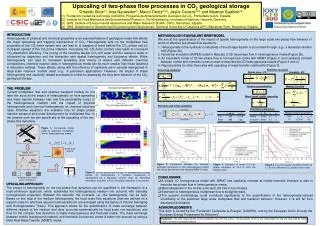
Upscaling of Geocellular Models for Flow Simulation Louis J. Durlofsky. Department of Petroleum Engineering, Stanford University ChevronTexaco ETC, San Ramon, CA. Acknowledgments. Yuguang Chen (Stanford University) Mathieu Prevost (now at Total) Xian-Huan Wen (ChevronTexaco)

E N D
Upscaling of Geocellular Models for Flow Simulation Louis J. Durlofsky Department of Petroleum Engineering, Stanford University ChevronTexaco ETC, San Ramon, CA
Acknowledgments • Yuguang Chen (Stanford University) • Mathieu Prevost (now at Total) • Xian-Huan Wen (ChevronTexaco) • Yalchin Efendiev (Texas A&M) (photo by Eric Flodin)
Outline • Issues and existing techniques • Adaptive local-global upscaling • Velocity reconstruction and multiscale solution • Generalized convection-diffusion transport model • Upscaling and flow-based grids (3D unstructured) • Outstanding issues and summary
Requirements/Challenges for Upscaling Injector Producer Producer Injector • Accuracy & Robustness • Retain geological realism in flow simulation • Valid for different types of reservoir heterogeneity • Applicable for varying flow scenarios (well conditions) • Efficiency
Existing Upscaling Techniques • Single-phase upscaling: flow(Q /p) • Local and global techniques (kk* or T*) • Multiphase upscaling: transport(oil cut) • Pseudo relative permeability model (krjkrj*) • “Multiscale” modeling • Upscaling of flow (pressure equation) • Fine scale solution of transport (saturation equation)
Local Upscaling to Calculate k* • Local BCs assumed: constant pressure difference • Insufficient for capturing large-scale connectivity in highly heterogeneous reservoirs or Local Extended Local Solve (kp)=0 over local region for coarse scale k * or T* Global domain
A New Approach Adaptive Local-Global Upscaling • New approach uses global coarse scalesolutions to determine appropriate boundary conditions for localk* or T* calculations • Efficiently captures effects of large scale flow • Avoids global fine scale simulation • Standard local upscaling methods unsuitable for highly heterogeneous reservoirs • Global upscaling methods exist, but require global fine scalesolutions (single-phase) and optimization
Adaptive Local-Global Upscaling (ALG) Local fine scale calculation Local fine scale calculation Coarse pressure Coarse pressure Interpolated pressure gives Local BCs Interpolated pressure gives local BCs Coarse scale properties k* or T* and upscaled well index • Thresholding: Local calculations only in high-flow regions (computational efficiency) Well-driven global coarse flow y x
Thresholding in ALG |qc| |qc|max Regions for Local calculations • Avoids nonphysical coarse scale properties (T *=q c/pc) • Coarse scale properties efficiently adapted to a given flow scenario Permeability Streamlines Coarse blocks • Identify high-flow region, > ( 0.1)
Multiscale Modeling • Solve flow on coarse scale, reconstruct fine scale v, solve transport on fine scale • Active research area in reservoir simulation: • Dual mesh method (FD): Ramè & Killough (1991), Guérillot & Verdière (1995), Gautier et al. (1999) • Multiscale FEM: Hou & Wu (1997) • Multiscale FVM: Jenny, Lee & Tchelepi (2003, 2004)
Reconstruction of Fine Scale Velocity Partition coarse flux to fine scale Solve local fine scale (kp)=0 Upscaling, global coarse scale flow Reconstructed fine scale v (downscaling) • Readily performed in upscaling framework
Results: Performance of ALG Pressure Distribution Averaged fine Q (Fine scale) = 20.86 ALG, Error: 4% Coarse: extended local Extended local, Error: 67% Coarse: Adaptive local-global Channelized layer (59) from 10th SPE CSP Upscaling 220 60 22 6 Flow rate for specified pressure • Fine scale:Q =20.86 • Extended T*: Q = 7.17 • ALG upscaling: Q = 20.01
Results: Multiple Channelized Layers Extended local T* Adaptive local-global T* 10th SPE CSP
Another Channelized System 100 realizations 120 120 24 24 k* only T* + NWSU ALG T*
Results: Multiple Realizations 100 realizations mean 90% conf. int. Fine scale • 100 realizations conditioned to seismic and well data • Oil-water flow, M=5 • Injector: injection rate constraint, Producer: bottom hole pressure constraint • Upscaling: 100 100 10 10 BHP (PSIA) Time (days)
Results: Multiple Realizations BHP (PSIA) BHP (PSIA) Time (days) Time (days) Coarse: Purely local upscaling Coarse: Adaptive local-global Mean(coarse scale) Mean (fine scale) 90% conf. int. (coarse scale) 90% conf. int. (fine scale)
Results (Fo): Channelized System Oil cut from reconstruction 220 60 22 6 ALG T* Flow rates • Fine scale:Q =6.30 • Extended T*: Q = 1.17 • ALG upscaling: Q = 6.26 Extended local T* Fine scale
Results (Sw): Channelized System Fine scale streamlines ReconstructedSwfrom ALG T *(22 6) 1.0 0.5 0.0 Fine scale Sw(220 60) ReconstructedSwfrom extended local T *(22 6)
Results for 3D Systems (SPE 10) 50 channelized layers, 3 wells pinj=1, pprod=0 Typical layers Upscale from 6022050 124410 using different methods
Results for Well Flow Rates - 3D Average errors • k* only: 43% • Extended T* + NWSU: 27% • Adaptive local-global: 3.5%
Results for Transport (Multiscale) - 3D Producer 1 Producer 2 fine scale local T* w/nw Fo Fo ALG T* standard k* standard k* fine scale local T* w/nw ALG T* PVI PVI • Quality of transport calculation depends on the accuracy of the upscaling
Velocity Reconstruction versus Subgrid Modeling • Multiscale methods carry fine and coarse grid information over the entire simulation • Subgrid modeling methods capture effects of fine grid velocity via upscaled transport functions: • - Pseudoization techniques • - Modeling of higher moments • - Generalized convection-diffusion model
Pseudo Relative Permeability Models • Coarse scale pressure and saturation equations of same form as fine scale equations • Pseudo functions may vary in each block and may be directional (even for single set of krj in fine scale model) * upscaled function c coarse scale p, S
Generalized Convection-Diffusion Subgrid Model for Two-Phase Flow • Pseudo relative permeability description is convenient but incomplete, additional functionality required in general • Generalized convection-diffusion model introduces new coarse scale terms • - Form derives from volume averaging and • homogenization procedures • - Method is local, avoids need to approximate • - Shares some similarities with earlier stochastic • approaches of Lenormand & coworkers (1998, 1999)
“primitive” term GCD term Generalized Convection-Diffusion Model • Coarse scale saturation equation: (modified convection m and diffusion D terms) • Coarse scale pressure equation: (modified form for total mobility, Sc dependence)
p = 1 S = 1 p = 0 Calculation of GCD Functions • D and W2 computed over purely local domain: (D and W2 account for local subgrid effects) • m and W1 computed using extended local domain: (m and W1 - subgrid effects due to longer range interactions) target coarse block
Solution Procedure • Generate fine model (100 100) of prescribed parameters • Form uniform coarse grid (10 10) and compute k* and directional GCD functions for each coarse block • Compute directional pseudo relative permeabilities via total mobility (Stone-type) method for each block • Solve saturation equation using second order TVD scheme, first order method for simulations with pseudo krj fine grid: lx lz Lx= Lz
lx = 0.25, lz= 0.01, s =2, side to side flow 100 x 100 10 x 10 (GCD) 10 x 10 (primitive) 10 x 10 (pseudo) Oil Cut PVI Oil Cuts for M =1 Simulations • GCD and pseudo models agree closely with fine scale (pseudoization technique selected on this basis)
Results for Two-Point Geostatistics • Diffusive effects only x =0.05, y = 0.01, logk = 2.0 10 5 0 100x100 10x10, Side Flow
Results for Two-Point Geostatistics (Cont’d) • Permeability with longer correlation length x =0.5, y = 0.05, logk = 2.0 10 5 0 100x100 10x10, Side Flow
p = 0 p = 0 Effect of Varying Global BCs (M =1) lx = 0.25, lz= 0.01, s =2 100 x 100 10 x 10 (GCD) 10 x 10 (primitive) 10 x 10 (pseudo) p = 1 S = 1 lx = 0.25, lz= 0.01, s =2 0 t 0.8 PVI Oil Cut p = 1 S = 1 t > 0.8 PVI PVI
100 x 100 10 x 10 (GCD) 10 x 10 (pseudo) Oil Cut Total Rate PVI PVI Corner to Corner Flow (M = 5) lx = 0.2, lz= 0.02, s =1.5 • Pseudo model shows considerable error, GCD model provides comparable agreement as in side to side flow
100 x 100 10 x 10 (GCD) 10 x 10 (pseudo) Oil Cut Total Rate PVI PVI Effect of Varying Global BCs (M = 5) lx = 0.2, lz= 0.02, s =1.5 • Pseudo model overpredicts oil recovery, GCD model in close agreement
100 x 100 10 x 10 (GCD) 10 x 10 (pseudo) Total Rate Oil Cut PVI PVI Effect of Varying Global BCs (M = 5) lx = 0.5, lz= 0.02, s =1.5 • GCD model underpredicts peak in oil cut, otherwise tracks fine grid solution
Combine GCD with ALG T* Upscaling Coarse scale flow: Pseudo functions: GCD model: T* from ALG, dependent on global flow *, m(Sc) and D(Sc) • Consistency between T* and * important for highly heterogeneous systems
ALG + Subgrid Model for Transport (GCD) • Stanford V model (layer 1) • Upscaling: 100130 1013 • Transport solved on coarse scale t 0.6 PVI t < 0.6 PVI flow rate oil cut
diagnostic Unstructured Modeling - Workflow fine model coarse model upscaling gridding info. maps Gocad interface flow simulation flow simulation
k i j Numerical Discretization Technique Primal and dual grids • CVFE method: • Locally conservative; flux on a face expressed as linear combination of pressures • Multiple point and two point flux approximations • Different upscaling techniques for MPFA and TPFA qij = a pi + b pj +c pk + ... or qij = Tij ( pi - pj )
3D Transmissibility Upscaling (TPFA) Dual cells Primal grid connection p=1 fitted extended regions p=0 <qij> Tij*= - <pj> <pi> - cell j cell i
cumulative frequency 1 Pb Pa b a min property max resolution constraint Sb Sa b a min max property Grid Generation: Parameters • Specify flow-diagnostic • Grid aspect ratio • Grid resolution constraint: • Information map (flow rate, tb) • Pa and Pb , sa and sb • N (number of nodes)
Unstructured Gridding and Upscaling velocity grid density Upscaled k* (from Prevost, 2003)
p=0 1 0. 5 p=1 0.25 Flow-Based Upscaling: Layered System • Layered system: 200 x 100 x 50 cells • Upscale permeability and transmissibility • Run k*-MPFA and T*-TPFA for M=1 • Compute errors in Q/Dp and L1 norm of Fw
Flow-Based Upscaling: Results 6 x 6 x 13 = 468 nodes 8 x 8 x 18 = 1152 nodes 1 1 Reference (fine) 0.8 TPFA 0.8 MPFA Fw Fw 0.6 0.6 0.4 0.4 0.2 0.2 0 0 0 0.2 0.4 0.6 0.8 1 0 0.2 0.4 0.6 0.8 1 PVI PVI (from M. Prevost, 2003)
sa log |V| grid size sb 1 reference uniform coarse (N=21x11x11=2541) 0.8 flow-rate adapted (N=1394) 0.6 Qc=0.99 Fw w F 0.4 Qc=0.82 0.2 0 0 0.2 0.4 0.6 0.8 1 PVI PVI Layered Reservoir: Flow Rate Adaptation • Grid density from flow rate • Flow results (Qf = 1.0) (from Prevost, 2003)
Summary • Upscaling is required to generate realistic coarse scale models for reservoir simulation • Described and applied a new adaptive local-global method for computing T * • Illustrated use of ALG upscaling in conjunction with multiscale modeling • Described GCD method for upscaling of transport • Presented approaches for flow-based gridding and upscaling for 3D unstructured systems
Future Directions • Hybridization of various upscaling techniques (e.g., flow-based gridding + ALG upscaling) • Further development for 3D unstructured systems • Linkage of single-phase gridding and upscaling approaches with two-phase upscaling methods • Dynamic updating of grid and coarse properties • Error modeling