IDE Interface
IDE Interface. Objectives. In this chapter, you will -Learn about each of the ATA standards (ATA-1 through ATA-6) used in PCs -Identify the ATA connector and cable -Learn how to properly install an IDE drive -Learn how to set jumpers for master, slave and cable select configurations

IDE Interface
E N D
Presentation Transcript
Objectives • In this chapter, you will • -Learn about each of the ATA standards (ATA-1 through ATA-6) used in PCs • -Identify the ATA connector and cable • -Learn how to properly install an IDE drive • -Learn how to set jumpers for master, slave and cable select configurations • -Understand how IDE transfer data • -Learn about the newest form of ATA-Serial ATA
IDE Interface • The primary interface used to connect a hard disk drive to a PC is typically called IDE ( Integrated Drive Electronics). • IDE refers to the fact that the interface electronics or controller is built into the drive and is not a separate board. • Although technically the correct name for the interface is ATA, many persist in using the IDE designation today. • The primary purpose of the hard disk controller, or interface, is to transmit and receive data to and from the drive.
IDE Interface • As mentioned earlier, IDE (now referred to as ATA) is a generic term that applies to any drive with a built in disk controller. • ATA is a 16-bit parallel interface, meaning that 16 bits are transmitted simultaneously down the interface. • A new interface called a serial ATA was officially introduced in late 2000.
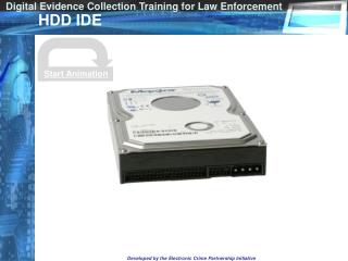
IDE Origins Sector Cluster • The earliest IDE drives were called hardcards and were nothing more than hard disks and controllers bolted together and plugged into a slot as a single unit. • Companies got the idea to redesign the controller to replace the logic board assembly on a standard hard disk and then mount it in a standard drive bay just like any other drive. Track
IDE Origins • Compaq was the first to incorporate a special bus adapter in its system to adapt the 98-pin AT(ISA) bus edge connector on the motherboard to a smaller 40-pin header-style connector.
IDE Bus Versions • Four main types of IDE interfaces have been based on three bus standards. • Serial AT Attachment (SATA) • Parallel AT Attachment (ATA) IDE based on 16 bit ISA • XT IDE (based on 8-bit ISA) • MCA IDE (based on 16-bit Micro Channel) • Of these,only the ATA versions are used today. • The improved versions of parallel ATA are referred to as ATA-2 and higher.
ATA IDE • Control Data Corporation, Western Digital, and Compaq created the first ATA-IDE interface drive and were first to establish the 40-pin ATA connector pinout.
ATA Standards • The ATA interface is controlled by an independent group of representatives from major PC, drive, and component manufacturers called Technical Committee T13. • They are responsible for all interface standards relating to the parallel AT Attachment storage interface. • A second group called the Serial ATA Workgroup has formed to create the Serial ATA Standards.
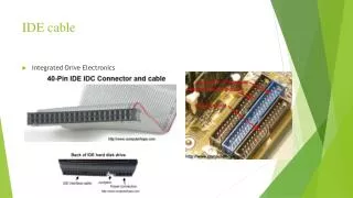
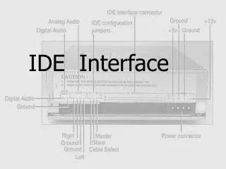
ATA I/O Connector • The ATA interface connector is normally a 40-pin header-type connector with pins spaced 0.1 inches apart and generally keyed to prevent the possibility of installing it upside down. • Plugging in an IDE cable backward usually won’t cause any permanent damage, however, it can lock up the system and prevent it from running at all.
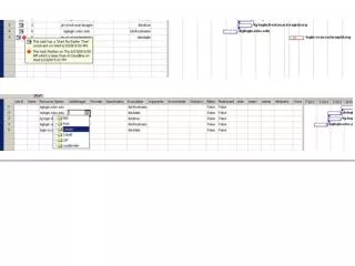
Dual Drive Configurations • Dual drive ATA installations can cause problems because each drive has its own controller and both controllers must function while being connected to the same bus. • The ATA standard provides the option of operating on the AT bus in a daisy-chained configuration. • The primary drive (drive 0) is called the master, and the secondary drive (drive 1) is called the slave.
Dual Drive Configurations • Most IDE drives can be configured with three settings. • The diagram illustrates the settings of master, slave, and cable select
ATA Commands • The ATA IDE interface was modeled after the WD1003 controller IBM used in the original AT system. • All ATA IDE drives must support the original WD command set (eight commands) with no exceptions. • All IBM compatible systems have built in ROM BIOS support for the WD1003, so they support ATA as well. • In addition, the ATA specification added numerous commands to enhance performance and capabilities.
Identity Drive Command • The Identity Drive command can tell you the following: • Number of cylinders • Number of heads • Number of sectors per track in the recommended translation mode • Number of cylinders in the current translation mode • Number of sectors per track in the current translation mode • Manufacturer and model number • Serial number • Buffer type
Serial ATA • With the introduction of ATA-6 it seems that the parallel ATA standard that has operated for the past ten years is running out of steam • Sending data at rates faster than 100mb/sec down a parallel cable has problems with signal timing, electromagnetic interference, and integrity. • The solution is in the serial ATA interface which is backward compatible with the parallel ATA.
SATA vs. Parallel ATA • You can’t plug parallel ATA drives into a serial ATA host adapters and vice versa. • The serial ATA uses much thinner cables with only 7 pins that are easier to plug in. • Configuration of serial ATA is also simpler because the jumper settings for master/ slave are no longer necessary.
ATA Raid • Raid is an acronym for redundant array of independent disks and was designed to improve the fault tolerance of computer storage systems. • To improve reliability and performance, scientists proposed 6 levels of RAID. • Currently there are seven layers of RAID called RAID 0 through 6.