Phasor Voltage-Current Relations in Circuits: Impedance & Admittance
230 likes | 249 Vues
Learn about impedance, admittance, steady-state sinusoidal analysis, and related educational materials. Understand how to apply impedance and admittance in circuit analysis.

Phasor Voltage-Current Relations in Circuits: Impedance & Admittance
E N D
Presentation Transcript
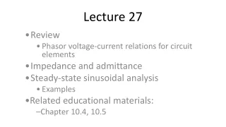
Lecture 27 Review Phasor voltage-current relations for circuit elements Impedance and admittance Steady-state sinusoidal analysis Examples Related educational materials: Chapter 10.4, 10.5
Impedance • Define the impedance, , of a circuit as: • Notes: • Impedance defines the relationship between the voltage and current phasors • The above equations are identical in form to Ohm’s Law • Units of impedance are ohms ()
Impedance – continued • Impedance is a complex number • Where • R is called the resistance • X is called the reactance • Impedance is not a phasor • There is no sinusoidal waveform it is describing
Circuit element impedances • Our phasor circuit element voltage-current relations can all be written in terms of impedances
Admittance • Admittance is the inverse of impedance • Admittance is a complex number • Where • G is called the conductance • B is called the susceptance
Why are impedance and admittance useful? • The analysis techniques we used for time domain analysis of resistive networks are applicable to phasor circuits • E.g. KVL, KCL, circuit reduction, nodal analysis, mesh analysis, Thevenin’s and Norton’s Theorems… • To apply these methods: • Impedances are substituted for resistance • Phasor voltages, currents are used in place of time domain voltages and currents
Steady state sinusoidal (AC) analysis • KVL, KCL apply directly to phasor circuits • Sum of voltage phasors around closed loop is zero • Sum of current phasors entering a node is zero • Circuit reduction methods apply directly to phasor circuits • Impedances in series, parallel combine exactly like resistors in series, parallel • Voltage, current divider formulas apply to phasor voltages, currents
AC analysis – continued • Nodal, mesh analyses apply to phasor circuits • Node voltages and mesh currents are phasors • Impedances replace resistances • Superposition applies in frequency domain • If multiple signals exist at different frequencies, superposition is the only valid frequency domain approach • Summation of individual contributions must be done in the time domain (unless all contributions have same frequency)
AC analysis – continued • Thévenin’s and Norton’s Theorems apply to phasor circuits • voc and isc become phasors ( and ) • The Thévenin resistance, RTH, becomes an impedance, • Maximum power transfer: • To provide maximum AC power to a load, the load impedance must be the complex conjugate of the Thévenin impedance
Example 1 • Determine i(t) and v(t), if vs(t) = 100cos(2500t)V
Example 2 • In the circuit below, vs(t) = 5cos(3t). Determine: (a) The equivalent impedance seen by the source (b) The current delivered by the source (c) The current i(t) through the capacitor
Example 2 – part (a) (a) Determine the impedance seen by the source
Example 2 – part (b) (b) Determine current delivered by the source
Example 2 – part (c) (c) Determine current i(t) through the capacitor
Example 3 • Use nodal analysis to determine the current phasors and if
; • On previous slide: • Set up reference node, independent node • Write KCL at independent node • Solve for node voltage
Example 3 – continued again • What are ic(t) and iR(t)? • What are ic(t) and iR(t) if the frequency of the input current is 5000 rad/sec?
Example 3 – revisited • Can example 3 be done more easily?
Example 4 • Use mesh analysis to determine .