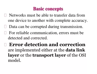
Basics of Analytical Instrumental Methods in Chemical Analysis
620 likes | 945 Vues
Understand the fundamental concepts of instrumental methods in chemical analysis, the relation between the analyte, stimulus, and measurement of change in observable property. Learn about analytical instruments and different types of methods used in analysis.

Basics of Analytical Instrumental Methods in Chemical Analysis
E N D
Presentation Transcript
Satish Pradhan Dnyanasadhana College, Thane Basic Concepts in Instrumental Methods By Dr. BhushanLangi
Basic Concepts in Instrumental Methods Relation between the Analyte, Stimulus and measurement of change in the observable property • Analyte: • It is a substance whose chemical constituents are being identified and measured. • There are highly efficient and sensitive chromatographic and electrophoretic techniques are used for the separation of the components of complex mixtures. • An instrument for chemical analysis converts information about the physical and chemical properties of the analyte into information which can be easily interpreted. • Thus, an analytical instrument is a communication device between the analyte and the investigator. • To get the desired information about the analyte, a stimulus must be provided which is usually in the form of energy - electromagnetic, electrical, mechanical or nuclear. • The stimulus produces a response from the analyte which can be measured and interpreted.
Block Diagram of an Analytical Instrument Source of Energy Analytical Instruments Analyte Under Study • The analytical instruments measure the response of the analyte to the radiation. • The response should be proportional to the concentration of the analyte.
A. Depending on Optical Properties: • Optical methods of analysis are based on the interaction of the analyte with radiation. • The components of a sample interact with radiation in different ways — absorption, emission, scattering etc. • Spectrophotometry: • Photoelectric Calorimeter, the amount of visible light absorbed depends on the concentration of the light absorbing component in the sample. • UV absorption is mostly used for identification of the components. • IR absorption is used for the elucidation of the structure of the component by identification of the functional groups present in the component. • In turbidimetry, the amount of light scattered by the analyte is used to determine its concentration in solution. • ii. Polarimetry: • Substances with asymmetric carbon atoms (Chiral carbons) rotate the plane of polarisation of polarised light. • This property of rotation of light is used in a polarimeter to determine the concentration of the optically active compound in solution.
e.g. Sucrose rotates the plane of polarisation of polarised light to the right (dextrorotatory) Glucose is also dextro-rotatory but fructose rotates the plane of polarisation to the left (laevo-rotatory). • B. Depending on Electrochemical Properties: • Electrochemical methods of analysis are based on the measurement of electrical properties of the sample. • i. Potentiometry: • In potentiometric measurements, the sample solution forms part of a galvanic cell. • The potential developed in the galvanic cell is related to the concentration of the sample solution. • In potentiometric titrations, the emf of the electrochemical cell set up is measured after the addition of successive instalments of the titrant. • The end point is determined from the graph of emf versus volume of the titrant. • eg. Acid-Base titrations
ii. Conductometry: • The conductance of the sample solution is measured and related to the concentration of the sample solution. • In conductometric titrations, the conductance of the solution is measured after the addition of successive instalments of the titrant • eg. Acid-Base titrations • iii. Voltammetry: • The sample under study is made a part of the electrolytic cell and the current passing through the cell is measured at different potentials. • The current measured is related to the concentration of the electroactive species present in solution. • This method again sub classified as • Polarography: • In this voltammetric technique, a substance is identified by measuring the electrical potential at which it is electrolytically deposited from its solution. • eg. estimation of metals present in a solution.
b) Amperometry: • In this voltammetric methods of analysis, the potential applied is kept constant and current passing through the electrolytic cell is measured after the addition of successive instalments of the titrant. • The end point is determined from the graph of current versus volume of titrant. Amperometric titrations are used for the estimation of several metallic analytes which can be deposited (reduced) on a mercury drop cathode. • eg. Bi3+ vs EDTA • Mg2+ vs 8-hydroxyquinoline • Pb2+ vs K2Cr2O7 • iv. Coulometry: • In this technique, the sample solution is made part of an electrolytic cell and electrolysis is carried out. • The quantity of electricity passed through the solution is correlated with the concentration of electrooxidized (or electro reduced) species in solution. • eg. electrogravimetry.
C. Depending on Thermal Properties: • In thermal analysis, some physical or chemical property of the sample is measured as a function of temperature. When matter is heated, it undergoes certain physical or chemical changes or both over a wide range of temperatures. • By determining the temperatures at which these changes occur, it is possible to characterise the components present in the sample and thus identify them. • Thermal methods are further classified as: • i) Thermal Gravimetric Analysis (TGA) or Thermogravity: • Analysisin which the mass of the sample is measured as a function of temperature. • ii) Different Thermal Analysis (DTA): • Analysis in which the difference in temperature between the sample (Ts) and a suitable reference material (Tr) is measured as a function of temperature. • The temperature difference, ΔT = Ts — Tr is measured at different temperatures.
iii) Differential Scanning Calorimetry (DSC): • Analysisin which the energy required to establish a zero temperature difference between the sample and reference material (ΔT = Ts - Tr = 0) is measured as a function of temperature. • iv) Thermometric Titrations (TT): • Analysisin which the changes in temperature are measured during the course of a titration • eg. acid-base titrations or complexometric titrations.
Spectroscopy: • Spectroscopy is the study of the interaction of matter with electromagnetic radiation. • When radiation is incident on atoms and molecules, a part of it is absorbed and the rest is transmitted (emitted). • The radiation absorbed by a molecule is used for performing different types of motion. • The amount of radiation absorbed depends on the concentration of the absorbing species in solution. • This absorption of radiation can be used to determine the chemical structure of the absorbing species. • Thus, spectroscopy can be considered as an important tool for the chemical analysis of molecules. • Radiation travels in the form of waves. • A wave is associated with three important wave properties - wavelength λ, frequency ν and wave number ν̅ which are correlated by the equation,
Basic Terms involved: • Energy of Light: • Electromagnetic Spectrum: It is used to indicates all types of electromagnetic radiations
Planck’s Quantum Theory of Radiation According to this theory, the emission and absorption of energy takes place not in a continuous manner but in discrete instalments called Quanta or Photon. Even the propagation of energy through space is discontinuous and takes place in quanta. Each quantum can be considered as a packet of energy equal to hν, where h is the Planck’s constant, 6.625 x 10⁻³⁴Js and ν is the frequency of the energy radiation in Hz (s-1). Thus,
2. Radiant Power P • Radiant power P is the energy of the radiation that reaches a given area per second. • 3. Intensity of Light • Intensity of light, I is defined as the number of photons of radiation incident per unit area per unit time. • Intensity is independent of the frequency or wavelength of the incident radiation. • Energy is given by the term, hv and hence depends on the frequency and wavelength of the radiation. • 4. Polychromatic and Monochromatic Light • A polychromatic beam of light contains radiation with several wavelengths • e.g. white light has several wavelengths in the range 380 — 780 nm, violet light has wavelengths in the range 380 - 435 nm and a beam of red light has wavelengths in the range 650 - 780 nm. • A monochromatic beam has radiation of a single wavelength • e.g. a violet beam of wavelength X = 395 nm, a red beam of wavelength X = 700 nm. Monochromatic beams are produced by using special devices called monochromators.
5. Absorbance: • It is defined as logarithm of reciprocal transmittance. It is also known as optical density. • 6. Wavelength of maximum absorption, λmax • Spectroscopic analysis of a substance is carried out using radiation of a particular wavelength which is absorbed to the maximum extent i.e. maximally. This wavelength is called the λmax of the substance. • The constituent structural groups in a molecule also absorb their own characteristic wavelengths. Thus, a substance may show strong absorption of several wavelengths depending on its structure. • Table below indicates the λmax values of important groups
7. Transmittance: • It is the fraction of incident radiation that is transmitted by the sample. • Beer Lambert’s Law • When a beam of light passes through an absorbing medium (solution) a part of the light is absorbed and the rest is transmitted. • The amount of light absorbed depends on the concentration of the solution and the length traversed by the light through the solution. • The quantitative relation between the amount of light absorbed, concentration and the length of the absorbing medium is governed by three laws - Lambert’s law, the Beer’s law and the Beer - Lambert’s law.
Lambert’s Law: This law state that “Equal fractions of the incident light are absorbed by successive layers having equal thicknessof the absorbing medium (the layers have the same thickness)”. Consider a layer of thickness dx absorb a small amount dI of the incident light. The fraction is proportional to the thickness of the layer dx. ----------------- (1) ----------------- (2) Where, I = intensity of the light incident on the layer and K1 = constant The negative sign indicates that due to absorption, the intensity of light decreases as it passes through the absorbing medium.
If, Io = initial intensity of the light incident on the absorbing medium of length l and It = intensity of the transmitted beam then by integrating equation (2) ----------------- (3) Converting to base 10 ----------------- (4)
Beer’s Law: This law state that “Equal fractions of the incident light are absorbed by successive layers having equal concentration of the absorbing medium”. Consider a layer of concentration dc absorb a small amount dI of the incident light. The fraction is proportional to the thickness of the layer dc. ----------------- (5) ----------------- (6) Where, I = intensity of the light incident on the layer and K2 = constant The negative sign indicates that due to absorption, the intensity of light decreases as it passes through the absorbing medium having total concentration c.
If, Io = initial intensity of the light incident on the absorbing medium of concentration c It = intensity of the transmitted beam then by integrating equation (6) ----------------- (7) Converting to base 10 ----------------- (8) The above equation is referred as Beer’s equation for absorption of light.
Beer-Lambert’s Law: A combination of Lambert’s law and Beer’s law results in the Beer - Lambert’s law which states “Equal fractions of the incident light are absorbed by successive layers of equal thickness and equal concentration of the absorbing medium”. From the Labert’s Law, From the Beer’s Law, By combining both equations,
----------------- (9) Where, a = K1 . K2 = constant = Absorptivity of absorbing medium c = concentration in mol dm-3 l = length of the absorbing medium in cm ----------------- (10) This is the combined mathematical equation of Beer-Lambert’s Law.
Validity of Beer—Lambert’s law: The Beer-Lambert’s law is strictly applicable to dilute solutions whose concentrations are below 10-2 M. Such solutions obey Beer-Lambert’s Law equation according to which absorbance is proportional to the concentration of the solution and transmittance is inversely proportional to the concentration. Beer - Lambert’s plots for dilute solutions Figure (a) showsa straight-line graph passing through the origin confirms that the absorbing species obeys Beer-Lambert’s law. The dotted curve I indicates a positive deviation from the law whereas curve II indicates a negative derivation.
Derivation from the Beer - Lambert’s law: • Deviations from Beer — Lambert’s law are of two types. • When the observed absorbance is greater than the expected value, it is called positive deviation and • When the observed absorbance is lesser than the expected value, it is called negative deviation. • The deviations can be broadly classified into three categories: • Real deviation • Instrumental deviations • Chemical deviations • Real Deviations • The linear relationship between absorbance and concentration of solution is observed only in dilute solution and does not hold true at concentrations above 10-2 M. • The molar absorptivity ε depends on the refractive index of the absorbing medium. The refractive index changes with the concentration of the absorbing solution. At high concentrations, these changes are considerable but at concentrations below 10-2 M, they can be neglected.
2. Instrumental Deviations • The light incident on the absorbing medium should be strictly monochromatic otherwise deviations from Beer-Lambert’s law are observed. • Monochromators are used to produce monochromatic beams which are absorbed to the maximum extent by the absorbing medium (λmax). • 3. Chemical deviations • The Beer Lambert’s law is not obeyed if the absorbing species undergoes dissociation, association or reaction in solution. • The molecules of the absorbing species should remain as simple molecules in solution and should not undergo any change in molecular condition. • Also the absorbing species should not react with the solvent.
Instrumentation for Absorption Spectroscopy Absorption Spectroscopy Colorimeter Spectrophotometer • Work in the visible region. • Used for quantitative analysis of coloured compounds which absorb visible light • Work in UV, Visible and IR regions. • Used for determination of the structure of colourless as well as coloured compounds in addition to quantitative analysis Single Beam Colorimeter Double Beam Colorimeter Single Beam Spectrophotometer Double Beam Spectrophotometer
Single Beam Photoelectric Colorimeter Principle: In a single beam colorimeter, a narrow band of wavelengths is incident on the absorbing sample. The absorbance (or percentage transmittance) of the sample is determined after adjusting the absorbance of the solvent (blank) to 0 (or 100% T) for the same band of wavelengths. All measurements are done using a single optical path for the beam of light. Diagram: Filter Holder
Construction: • A photoelectric colorimeter has the following components: • A source of visible light e.g. an incandescent lamp with a tungsten filament. The filament on electrical heating emits visible radiation. • The emerging beam is collimated using a convex lens. • A colour filter which selects a narrow band of wavelengths which enters a fine slit and is then incident on the sample. • A sample holder called cuvette. It is a rectangular transparent container of glass or quartz. Sample holders in test tube form are also widely used. Most sample holders have a standard path length of 1 cm. • A photocell or transducer which converts the transmitted beam emerging from the sample into an electrical current. This electrical pulse is due to the emission of electrons from the photoelectrode surface caused by the transmitted beam falling on the photoelectrode. • A read-out system like a dial to directly read A or % T of sample. The read out system is needed because the electrical current from the photocell has to be converted into the absorbance or percentage transmittance of the sample.
Working: • The cuvette is first filled with the solvent and the % T is adjusted to 100%(or A is adjusted to 0). • Then the cuvette is filled with the sample solution and its % T (or A) is determined. • The concentration of the sample solution can then be found out using Beer—Lambert’s equation.
Details of Major Components: • Colour Filters: • They are of two types: • Glass filters: A glass filter is a solid sheet of glass which is coloured by dissolving or dispersing a pigment in the glass. • Interference filters: • An interference filter consists of two thin films of silver separated by a film of transparent material of low refractive index. • Light undergoes interference at the silver surface. • The unwanted wavelengths are removed by selective reflection and only the required wavelengths pass out of the filter. • Interference filters give narrow bands of wavelengths as compared to glass filters. • The absorbance of the sample is first determined using the different colour filters. • The filter giving maximum absorbance or minimum % T is chosen for use in the colorimeter.
2. Detectors • Photoemissive Cell: A photoemissive cell consists of an evacuated glass tube fitted with a photosensitive cesium cathode. A metal wire functions as the collector anode. When light falls on this cathode, electrons are emitted which pass over to the anode. A potential difference of 100 volts is maintained between the two electrodes. The electric current produced can be amplified and is proportional to the amount of light falling on the photocathode. The output of the amplifier is recorded on a dial on which the absorbance or % T can be directly read. Colorimeter
b) Photomultiplier Tube (PMT): • Construction: • Photomultiplier tube is an evacuated tube having photocathode at one end. • The tube having series of electrodes inside. These electrodes are known as dynodes. • Both photocathode and dynodes are made up from Arsenic or Antimony. • Dynodes are arranged in such a way that each dynode having increasing potential than previous dynode.
Working: • When radiation strikes photocathode of PMT electrons are ejected from the surface of photocathode due to photoelectric effect. • These negatively charged electrons are travel towards positively charged dynodes. • From one electron 10 secondary electrons are formed at each dynode. Thus, electron from photocathode incident on 1st dynode form number of secondary electrons at dynode. • The process is repeated at 2nd dynode and again more number of secondary electrons are form at 2nd dynode. • Thus, as number of dynode increased number of secondary electrons also increased. • Finally, all electrons collected by collector electrode.
Photovoltaic or Barrier Layer Cell: Photovoltaic cells are most commonly used in colorimeters. • Construction: • A barrier cell consists of an iron plate (A) on which a thin layer of a semiconductor like selenium (B) is deposited. • A very thin layer of silver (C) is sputtered on the selenium layer to serve as the collector electrode. • The iron plate serves as the second electrode. The silver film is mechanically strengthened by an iron ring D.
Working: • The transmitted light from the sample emits electrons from the selenium surface. • These electrons pass through an imaginary or hypothetical barrier or gap in between the selenium and silver layers and are then collected by the silver collector electrode. • Thus under the influence of light, a cell is formed with the iron plate (A) as positive electrode and the metal ring (D) as negative electrode. • This type of cell generates its own emf and no external power supply is required for the flow of current. • If the cell is connected to a galvanometer, a current will flow provided the resistance in the external circuit is small. • The electrical current is proportional to the amount of light falling on the selenium surface.
Double Beam Photoelectric Colorimeter: Principle: In such colourimeter beam of light splits into two identical beams one passing through the sample and the other passing through the solvent (blank). Diagram:
Construction: A source of visible light e.g. an incandescent lamp with a tungsten filament. The emerging beam is collimated using a convex lens. A colour filter which selects a narrow band of wavelengths A mirror splits this narrow band into two identical beams-one passing through the sample and the other passing through the solvent (blank). The sample absorbs a part of the beam whereas the solvent transmits it completely. A sample holder called cuvette. It is a rectangular transparent container of glass or quartz. Sample solution is held in sample holder. Blank Cuvette used to hold the solvent. The two beams then fall on the respective photocells where photoelectrons are emitted.The two electric currents thus produced pass through the variable resistances - resistance AB for the current coming from the solvent side and resistance CD for the current coming from the sample side. A potential gradient is set up across AB and CD depending on the two currents. AB is calibrated to read % T (or absorbance). A galvanometer connected across the two resistances serves as the null indicator.
Working: The solvent is first taken in both the cuvettes. Jockey J1 is set at point A(100% T). Jockey J2 is adjusted along CD till there is no current flow as indicated by the null in the sensitive galvanometer. The sample is then placed in the sample cuvette. It absorbs a part of the light and the transmitted beam emerging from it falls on the photocell. This beam has less intensity than when only solvent was present in the sample cuvette. Hence there will be a proportionate decrease in the electric current produced in the photo-cell and the voltage across CD decreases. As a result, the null in the galvanometer is disturbed. Now Jockey J1 is moved along AB to a lower value so that the null is restored; The %T is directly read on the scale when the null is restored.
Double beam photometers have several advantages over single beam photometers. • Changes in the intensity of incident light due to voltage fluctuations in the power supply are compensated by splitting the incident beam into two identical beams by the use of a mirror and two balanced photocells. • Any errors due to solvent or impurity are balanced out as identical beams pass through the blank and the sample and the absorbance of blank is initially adjusted to zero. • The readings are not affected by changes in sensitivity of photocells or galvanometer as the null method is used. • The scale readings of the instrument are linear with the concentration of the sample solution.
Single Beam Spectrophotometer: Principle: In this instrument, a monochromator i.e. prism or diffraction grating produces a monochromatic beam which is then made incident on the sample. The absorbance A (or % T) of the sample solution is determined for different wavelengths after adjusting the absorbance (or % T) of the blank to zero (or 100% T) for each of the wavelengths. All measurements are done using a single optical path for the monochromatic beam of light. Diagram:
Construction: • A single beam spectrophotometer has the following components: • Sources of Radiation: A tungsten lamp is used for obtaining visible light. U.V. light is obtained from a hydrogen or deuterium discharge lamp. • Monochromator: A monochromator, either a prism or diffraction grating disperses the light into its constituent wavelengths. By rotating the monochromator, the different wavelengths are focused one by one on the sample. • Sample Holder (Sample cell): Glass cuvettes are used in the visible region. Quartz cuvettes are used in the U.V. region since glass absorbs U.V. light. • Photocell: The transmitted beam emerging from the sample falls on the photocell. An electric current is produced due to the photo-emission of electrons at the photocathode. If this current is small, it can be amplified using an electronic amplifier. • Read Out Device: It is a dial on which absorbance A or % T can be directly read or a digital display.
Working: The sample holder is filled with the solvent (blank). The absorbance A value (or % T) of the solvent is adjusted to 0 (or 100 % T) for a particular wavelength, obtained by the rotation of the monochromator. The sample is then taken in the sample holder and its A value (or % T) is determined for the same wavelength. The procedure is repeated for different wavelengths obtained by the rotation of the monochromator. The A (or % T) values can be read either on a dial or a digital display. The λmax values for the sample can thus be found out.
Details of Major Components: • Monochromators: • Monochromators are dispersing devices which split a beam of light into its constituent wavelengths. • Monochromators are of two types viz.Prisms and Diffraction gratings • a) Prism: The collimated beam is dispersed by the prism into its constituent wavelengths. The prism is rotated to allow a particular wavelength to fall on a focusing lens and then emerge out of an exit slit. The slit width controls the band width of thebeam. It is observed that the dispersion is greater for short wavelengths and smaller for long wavelengths. Hence the slit width is increased for short wavelengths and decreased for long wavelengths. Glass prism are used in the visible region whereas quartz prisms are used in the U.V. region.
b) Diffraction Gratings: A diffraction grating is made by cutting a large number of perfectly parallel straight lines (grooves) into an aluminium surface. For the U.V. and visible regions, 15000 - 30000 lines are ruled per inch. When the light is reflected at the grating surface, dispersion takes place due to the constructive interference of the reflected rays. The net path difference between two rays is an integral multiple of the wavelength and is given by the equation; Net path difference = nλ = d (sini ± sin θ) Where, n = order of interference and is a positive integer λ = wavelength of the incident light d = distance between two successive grooves (i.e. grating constant), i = angle of incidence of the beam θ = angle of reflection of the emergent beam.
The positive sign indicates that the incident and emergent beams are on the same side of the grating normal and negative sign indicates that the two beams are on either side of the grating normal. • Angle θ is different for different wavelengths. Thus, the light is dispersed into its constituent wavelengths at the grating surface. • Grating monochromators have certain district advantages over prisms. • A grating gives a much better dispersion of light than a prism. • Gratings are made of non-corrosive materials like aluminium which are not easily attacked by moisture. • Gratings can be used over a longer wavelength range as compared to prisms.
Double Beam Spectrophotometer: Principle: In the double beam spectrophotometer, the monochromatic beam coming from the diffraction grating monochromator is split into two beams by means of mirror M1. The reference beam is reflected by mirror M2 into the blank cell containing the solvent and the sample beam passes into the sample cell. Diagram:
Construction: An optical attenuator mounted in the path of the reference beam reduces its intensity to match that of the sample beam i.e. the amount of transmitted light coming from the blank is decreased so that its intensity is equal to that of the transmitted light coming from the sample. The attenuator is connected to a recorder pen which moves across the chart paper wound on a rotating drum. The two beams are then reflected by mirrors M3 and M4 into a suitable detector. Photocells are used as detectors in the U.V. and Visible regions. The detector produces an electrical current which is proportional to the radiation received by it. The electric current is magnified by use of an electronic amplifier and the electric signal is sent to the recorder pen. A motor synchronizes the speed of the rotating monochromator with that of the rotating drum carrying the chart paper. As a result, the wavelength marked on the chart is identical with that received by the detector.
Working: The monochromator is rotated to allow different wavelengths to fall on the blank and sample. The process is called scanning. The recorder pen plots a graph ofabsorbance or % T versus wavelength (λ), frequency (ν) or wave number ( ν̅ ) on the rotating drum. The wavelengths at which maximum absorption occurs are noted from the respective spectra and the groups responsible for these absorptions or transmissions are identified. Thus the structure of the sample can be elucidated from spectrum analysis.
Comparison between Photometers and Spectrophotometer • Photometers usually work in the visible range while spectrophotometers can be used in U.V., visible and IR regions. • Photometers use colour filters which allow a band of wavelengths of the complementary colour of the sample to be incident on the sample. Spectrophotometers employ monochromators (prisms or diffracting gratings) which produce perfectly monochromatic beams hence spectrophotometric analysis is more accurate as the band width of the light beam is minimum. Further, the Beer Lambert's law is strictly obeyed for the monochromatic beams used in spectrophotometers. • Photometers are generally used for quantitative analysis of coloured compounds whereas spectrophotometers are used for structure determination of colourless as well as coloured compounds in addition to quantitative analysis. • Spectrophotometers are much more costly than photometers.
Applications of UV - Visible Spectrophotometry • Identification of Structural Groups in Molecules Spectroscopic analysis of a substance is carried out using radiation of a particular wavelength which is absorbed to the maximum extent. This wavelength is called the λmax of the substance. Spectrum of the unknown compound is matched with the known. If each end every peak of the two spectra match, then the compound can be identified. U.V. visible spectra alone is very rarely used for identification of a compound. However, it is used for the detection of functional groups.