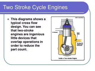
Four stroke cycle theory
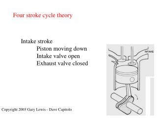
Four stroke cycle theory. Intake stroke Piston moving down Intake valve open Exhaust valve closed. Copyright 2003 Gary Lewis - Dave Capitolo. Four stroke cycle theory. Compression stroke Piston moving up Intake valve closed Exhaust valve closed. Four stroke cycle theory.

Four stroke cycle theory
E N D
Presentation Transcript
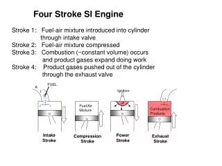
Four stroke cycle theory Intake stroke Piston moving down Intake valve open Exhaust valve closed Copyright 2003 Gary Lewis - Dave Capitolo
Four stroke cycle theory Compression stroke Piston moving up Intake valve closed Exhaust valve closed
Four stroke cycle theory Power stroke Piston moving down Intake valve closed Exhaust valve closed
Four stroke cycle theory Exhaust stroke Piston moving up Intake valve closed Exhaust valve open
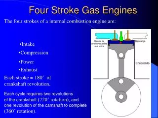
Four stroke cycle theory Each stroke takes 180° of crankshaft rotation to complete All cylinders fire in 720° of crankshaft rotation 720 divided by number of cylinders = firing interval Odd fire V-6 engine (90° block with 120° rod journals)
Piston dwell time Piston travel is at a minimum. . . TDC and BDC Crank moves horizontally Piston velocity Maximum when rod is 90° to crank Acceleration Maximum 30° earlier Best VE is obtained by synchronizing valve opening with piston speeds
Other engine cycles Overlap Both valves are open End of exhaust & start of intake Low pressure in exhaust port Blowdown Exhaust valve opens before BDC To help evacuate cylinder before piston reverses Pumping losses at end of exhaust stroke
Valve events Intake valve opening BTDC Low pressure in cylinder Intake valve closing ABDC Cylinder pressure is effected by timing Exhaust valve opening BBDC Residual pressure helps blowdown Exhaust valve closing ATDC Low pressure in exhaust port draws air in
Effects on valve timing Intake valve opening Late – Reduced VE Early – Dilution of intake with exhaust Intake valve closing Late – Reduces cylinder pressure Early – Increases cylinder pressure Exhaust valve opening Late – Pumping losses Early – Power reduction Exhaust valve closing Late – Reduces vacuum Early – Reduces VE
Combustion Spark ignition Maximum cylinder pressure 15° ATDC Tumble and swirl Motion reduces misfires Excess motion inhibits flow AFR 14.7:1 at part throttle, 12.5:1 under load Compression ignition 18:1 direct injection 23:1 pre-chambers for better starting Compression heats to 800-1200 °F
Diesel fuels Cetane volatility numbers 50-55 Higher cetane #1 fuel for cold weather Lower cetane #2 fuel for warm weather Paraffin separates from fuel at 20°F
Valve trains OHV (overhead valve) Pushrod configuration Many reciprocating parts Higher valve spring pressure required Compact engine size compared to OHC
Valve trains OHC (overhead cam) Fewer reciprocating parts Reduced valve spring pressure required Higher RPM capability Cylinder head assemblies are taller
Valve trains Cam-in-head No pushrods Use rocker arms
Valve lash compensators Solid lifters No internal parts Periodic adjustment
Valve lash compensators Hydraulic lifters To maintain zero lash Quieter No periodic adjustment Anti-scuff additives are required in oils
Hydraulic lifter operation • Valve closed • Oil flows through lifter bore, & • past check valve • Plunger return spring maintains • zero lash
Hydraulic lifter operation • Valve open • Check valve seats and limits the slippage • Now operates as a solid lifter
Hydraulic lifter operation • Return to valve closed • New oil enters the lifter body • This oil replaces oil that has leaked between • plunger and body (predetermined leakage)
Metering device Metering valve meters the oil flow to the pushrod
Timing sets • Gear sets • Cam and crank rotate in opposite directions • Noisy if not free of burrs • Helical and spur cut gears
Timing sets • Timing chains • Single and double roller • Tensioners
Timing sets • Timing belts • Require maintenance • Quiet
Camshaft terminology Cam lift (A-B) Valve lift = Cam lift times rocker ratio Valve lift .300” cam lift times 1.5 rocker ratio = .450” valve opening
Engine oiling Lubrication through pressure. . .
Engine oiling and spray. . .
Engine oiling • Oil pan baffles • To keep oil in sump during braking, • accelerating, and cornering
Engine oiling • Oil pan windage tray • To prevent oil aeration in the sump
Engine oiling • Oil pumps • Driven by distributors, gear on camshaft, or crankshaft
Engine oiling • Oil pumps with pressure relief valves • Gear type pump • Rotor type pump
Engine oiling • Full flow oil filtering system • Oil pump output flows • through filter first • Bypass circuit for restricted • filters will allow oil to • flow to engine
Engine oils API, SAE, and ASTM “S” - Spark ignition “C” - Compression ignition
Engine oil additives • Viscosity index improvers • To reduce viscosity change with heat • Detergents • To dissolve varnish and sludge • Dispersants • To keep sludge, carbon and other materials from • recombining and suspends them in oil to be drained • Scuff inhibitors • To reduce friction and wear • Antifoam and antioxidants • To prevent foaming and to slow oxidation in oil
Engine measurements • Bore • Diameter of cylinder • Stroke • Distance between TDC & BDC
Engine measurements • Displacement per cylinder • r² S • Displacement for the engine • Disp per cylinder times the • Number of cylinders
Engine measurements • Compression ratio • D + CV • CV • To calculate clearance volume • D . • CR-1
Engine measurements • Deck clearance • Top of piston to top of block deck • Measured with dial indicator or depth mic
Engine measurements • Deck height • Center line of crank to block deck
Fits and clearances • Running fit • Clearance between bearing and shaft • Clearance for oil • Listed as diametral
Fits and clearances • Interference (press) fit • OD is larger than ID • Example is piston pin pressed into rod
Fits and clearances of pistons • Full floating • .0003 - .0005 clearance in rod • .0001 - .0003 clearance in piston • Press Fit • .0008 - .0012 interference in rod • .0003 - .0005 clearance in piston • Rod offset • Beam offset to center of cylinder • Enlarged chamfers to clear fillets • Pin offset • Offset to major thrust side • Quieter engine, less cylinder wear
Cooling system operation • Engine heat is transfered . . . • through walls of the combustion chambers • through the walls of cylinders • Coolant flows . . . • to upper radiator hose • through radiator • to water pump • through engine water jackets • through thermostat • back to radiator
Cooling system operation • Fans increase air flow through radiator • Hydraulic fan clutches • Hydraulic fans consume 6 to 8 HP • Electric fans • Coolant (ethylene glycol) • 50/50 mixture increases boiling point to 227°F • pressurizing system to 15 PSI increases to 265°F • Coolant (propylene glycol) • Less protection at the same temperatures • Less toxic
Combustion efficiency • Under perfect conditions . . . • Only byproducts would be carbon dioxide and water • Iso-octane fuel is laboratory fuel • Because conditions are not perfect . . . • Carbon monoxide and hydrocarbons are produced • Oxides of nitrogen are produced from pressure & temp • Emission controls • Catalytic converters – Convert CO & HC to • carbon dioxide & water • O2 sensors – To monitor oxygen content in exhaust • EGR – To reduce peak cylinder temperatures
Cooling system operation • Heat energy • 1/3 usable power • 1/3 released through exhaust system • 1/3 released through cooling system • Engine temperature • Cool enough to prevent part failure • Warm enough to maximize engine efficiency
Four stroke diesel theory Compression ignition Uses high compression ratios instead of spark plugs Engine components are more robust Diesel fuel low has volatility
Four stroke diesel theory Compression ignition fuel system • Transfer pump from tank • Injection pump to injectors • Amount of fuel injected varies engine speed • Diesels have no throttle (always WOT) • AFR varies from 85:1 to 20:1
Four stroke diesel theory Indirect Injection • Indirect injection begins in a pre-chamber • Initial combustion takes place there • Slows the rate of combustion to reduce noise • Glow plugs are needed to provide heat
Four stroke diesel theory Direct Injection • Fuel is injected directly into cylinder • The piston has a chamber built into it • More reliable than indirect • More noisy than indirect