Optics
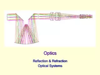
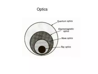
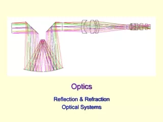
Optics. Reflection Diffuse reflection Refraction Index of refraction Speed of light Snell’s law Geometry problems Critical angle Total internal reflection Brewster angle Fiber optics Mirages Dispersion. Prisms Rainbows Plane mirrors Spherical aberration


Optics
E N D
Presentation Transcript
Optics • Reflection • Diffuse reflection • Refraction • Index of refraction • Speed of light • Snell’s law • Geometry problems • Critical angle • Total internal reflection • Brewster angle • Fiber optics • Mirages • Dispersion • Prisms • Rainbows • Plane mirrors • Spherical aberration • Concave and convex mirrors • Focal length & radius of curvature • Mirror / lens equation • Convex and concave lenses • Human eye • Chromatic aberration • Telescopes • Huygens’ principle • Diffraction
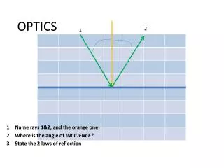
Reflection Most things we see are thanks to reflections, since most objects don’t produce their own visible light. Much of the light incident on an object is absorbed but some is reflected. the wavelengths of the reflected light determine the colors we see. When white light hits an apple, for instance, primarily red wavelengths are reflected, while much of the others are absorbed. A ray of light heading towards an object is called an incident ray. If it reflects off the object, it is called a reflected ray. A perpendicular line drawn at any point on a surface is called a normal (just like with normal force). The angle between the incident ray and normal is called the angle of incidence, i, and the angle between the reflected ray and the normal ray is called the angle of reflection, r. The law of reflection states that the angle of incidence is always equal to the angle of reflection.
Law of Reflection Normal line (perpendicular to surface) r i reflected rays incident rays i = r
Diffuse Reflection Diffuse reflection is when light bounces off a non-smooth surface. Each ray of light still obeys the law of reflection, but because the surface is not smooth, the normal can point in a different for every ray. If many light rays strike a non-smooth surface, they could be reflected in many different directions. This explains how we can see objects even when it seems the light shining upon it should not reflect in the direction of our eyes. It also helps to explain glare on wet roads: Water fills in and smoothes out the rough road surface so that the road becomes more like a mirror.
Speed of Light & Refraction As you have already learned, light is extremely fast, about 3108 m/s in a vacuum. Light, however, is slowed down by the presence of matter. The extent to which this occurs depends on what the light is traveling through. Light travels at about 3/4 of its vacuum speed (0.75 c) in water and about 2/3 its vacuum speed (0.67 c) in glass. The reason for this slowing is because when light strikes an atom it must interact with its electron cloud. If light travels from one medium to another, and if the speeds in these media differ, then light is subject to refraction (a changing of direction at the interface). Refraction of light waves Refraction of light rays
At an interface between two media, both reflection and refraction can occur. The angles of incidence, reflection, and refraction are all measured with respect to the normal. The angles of incidence and reflection are always the same. If light speeds up upon entering a new medium, the angle of refraction, r, will be greater than the angle of incidence, as depicted on the left. If the light slows down in the new medium, r will be less than the angle of incidence, as shown on the right. Reflection & Refraction Reflected Ray Reflected Ray Incident Ray Incident Ray r Refracted Ray normal normal Refracted Ray r
Axle Analogy Imagine you’re on a skateboard heading from the sidewalk toward some grass at an angle. Your front axle is depicted before and after entering the grass. Your right contacts the grass first and slows, but your left wheel is still moving quickly on the sidewalk. This causes a turn toward the normal. If you skated from grass to sidewalk, the same path would be followed. In this case your right wheel would reach the sidewalk first and speed up, but your left wheel would still be moving more slowly. The result this time would be turning away from the normal. Skating from sidewalk to grass is like light traveling from air to a more overhead view “optically dense” medium like glass or water. The slower light travels in the new medium, the more it bends toward the normal. Light traveling from water to air speeds up and bends away from the normal. As with a skateboard, light traveling along the normal will change speed but not direction. sidewalk grass r
c v n = Index of Refraction, n The index of refraction of a substance is the ratio of the speed in light in a vacuum to the speed of light in that substance: Medium Vacuum Air (STP) Water (20º C) Ethanol Glass Diamond n 1 1.00029 1.33 1.36 ~1.5 2.42 n = Index of Refraction c = Speed of light in vacuum v = Speed of light in medium Note that a large index of refraction corresponds to a relatively slow light speed in that medium.
Snell’s Law i ni nr r Snell’s law states that a ray of light bends in such a way that the ratio of the sine of the angle of incidence to the sine of the angle of refraction is constant. Mathematically, nisini = nr sinr Here ni is the index of refraction in the original medium and nr is the index in the medium the light enters. iandrare the angles of incidence and refraction, respectively. Willebrord Snell
1 A • n1 x A d B • • y n2 • B 2 Two parallel rays are shown. Points A and B are directly opposite one another. The top pair is at one point in time, and the bottom pair after time t. The dashed lines connecting the pairs are perpendicular to the rays. In time t, point A travels a distance x, while point B travels a distance y. sin1= x/d, so x = d sin1 sin2 = y/d, so y = d sin2 Speed of A: v1 = x/ t Speed of B: v2 = y/ t Snell’s Law Derivation Continued…
1 A • n1 x A d B • • y n2 • B 2 Snell’s Law Derivation (cont.) v1 x/t x sin1 = = = So, v2 y/t y sin2 v1/c sin11/n1sin1n2 = = = v2/c sin21/n2sin2 n1 n1 sin1 = n2 sin2
Refraction Problem #1 Goal: Find the angular displacement of the ray after having passed through the prism. Hints: • Find the first angle of refraction using Snell’s law. • Find angle ø. (Hint: Use Geometry skills.) • 3. Find the second angle of incidence. • Find the second angle of refraction, , using Snell’s Law 19.4712º 79.4712º Air, n1 = 1 30° 10.5288º Horiz. ray, parallel to base ø 15.9º Glass, n2 = 1.5
Refraction Problem #2 Goal: Find the distance the light ray displaced due to the thick window and how much time it spends in the glass. Some hints are given. 20º 1 1. Find 1 (just for fun). 2. To show incoming & outgoing rays are parallel, find . 3. Find d. 4. Find the time the light spends in the glass. Extra practice: Find if bottom medium is replaced with air. 20º H20 n1 = 1.3 20º 0.504 m glass 10m n2 = 1.5 5.2 ·10-8 s d H20 26.4º
Refraction Problem #3 Goal: Find the exit angle relative to the horizontal. 19.8° = 36° air = ? glass The triangle is isosceles.Incident ray is horizontal, parallel to the base.
Reflection Problem Goal: Find incident angle relative to horizontal so that reflected ray will be vertical. = 10º 50º center of semicircular mirror with horizontal base
n2 n1 b b Brewster Angle The Brewster angle is the angle of incidence the produces reflected and refracted rays that are perpendicular. From Snell, n1 sinb = n2 sin. α = b since + =90º, andb + =90º. β= since + =90º, and + = 90º. Thus, n1 sinb = n2 sin = n2 sin = n2 cosb tanb = n2/n1 Sir David Brewster
Critical Angle The incident angle that causes the refracted ray to skim right along the boundary of a substance is known as the critical angle, c. The critical angle is the angle of incidence that produces an angle of refraction of 90º. If the angle of incidence exceeds the critical angle, the ray is completely reflected and does not enter the new medium. A critical angle only exists when light is attempting to penetrate a medium of higher optical density than it is currently traveling in. nr ni c From Snell, n1 sinc = n2 sin90 Since sin90 = 1, we haven1 sinc = n2 and the critical angle is nr c = sin-1 ni
Critical Angle Sample Problem Calculate the critical angle for the diamond-air boundary. Refer to the Index of Refraction chart for the information. c =sin-1(nr /ni) = sin-1(1/2.42) =24.4 Any light shone on this boundary beyond this angle will be reflected back into the diamond. air diamond c
Total Internal Reflection Total internal reflection occurs when light attempts to pass from a more optically dense medium to a less optically dense medium at an angle greater than the critical angle. When this occurs there is no refraction, only reflection. n1 n2 > n1 n2 > c Total internal reflection can be used for practical applications like fiber optics.
Fiber Optics Fiber optic lines are strands of glass or transparent fibers that allows the transmission of light and digital information over long distances. They are used for the telephone system, the cable TV system, the internet, medical imaging, and mechanical engineering inspection. spool of optical fiber Optical fibers have many advantages over copper wires. They are less expensive, thinner, lightweight, and more flexible. They aren’t flammable since they use light signals instead of electric signals. Light signals from one fiber do not interfere with signals in nearby fibers, which means clearer TV reception or phone conversations. A fiber optic wire Continued…
Fiber Optics Cont. Fiber optics are often long strands of very pure glass. They are very thin, about the size of a human hair. Hundreds to thousands of them are arranged in bundles (optical cables) that can transmit light great distances. There are three main parts to an optical fiber: • Core- the thin glass center where light travels. • Cladding- optical material (with a lower index of refraction than the core) that surrounds the core that reflects light back into the core. • Buffer Coating- plastic coating on the outside of an optical fiber to protect it from damage. Continued…
Light travels through the core of a fiber optic by continually reflecting off of the cladding. Due to total internal reflection, the cladding does not absorb any of the light, allowing the light to travel over great distances. Some of the light signal will degrade over time due to impurities in the glass. Fiber Optics (cont.) There are two types of optical fibers: • Single-mode fibers-transmit one signal per fiber (used in cable TV and telephones). • Multi-mode fibers- transmit multiple signals per fiber (used in computer networks).
Mirage Pictures Mirages
Mirages Mirages are caused by the refracting properties of a non-uniform atmosphere. Several examples of mirages include seeing “puddles” ahead on a hot highway or in a desert and the lingering daylight after the sun is below the horizon. More Mirages Continued…
Inferior Mirages A person sees a puddle ahead on the hot highway because the road heats the air above it, while the air farther above the road stays cool. Instead of just two layers, hot and cool, there are really many layers, each slightly hotter than the layer above it. The cooler air has a slightly higher index of refraction than the warm air beneath it. Rays of light coming toward the road gradually refract further from the normal, more parallel to the road. (Imagine the wheels and axle: on a light ray coming from the sky, the left wheel is always in slightly warmer air than the right wheel, so the left wheel continually moves faster, bending the axle more and more toward the observer.) When a ray is bent enough, it surpasses the critical angle and reflects. The ray continues to refract as it heads toward the observer. The “puddle” is really just an inverted image of the sky above. This is an example of an inferior mirage, since the cool are is above the hot air.
Superior Mirages Superior mirages occur when a layer of cool air is beneath a layer of warm air. Light rays are bent downward, which can make an object seem to be higher in the air and inverted. (Imagine the wheels and axle on a ray coming from the boat: the right wheel is continually in slightly warmer air than the left wheel. Thus, the right wheel moves slightly faster and bends the axle toward the observer.) When the critical angle is exceeded the ray reflects. These mirages usually occur over ice, snow, or cold water. Sometimes superior images are produced without reflection. Eric the Red, for example, was able to see Greenland while it was below the horizon due to the light gradually refracting and following the curvature of the Earth.
Lingering daylight after the sun is below the horizon is another effect of refraction. Light travels at a slightly slower speed in Earth’s atmosphere than in space. As a result, sunlight is refracted by the atmosphere. In the morning, this refraction causes sunlight to reach us before the sun is actually above the horizon. In the evening, the Sunlight after Sunset Apparent position of sun Observer Actual position of sun Earth Atmosphere sunlight is bent above the horizon after the sun has actually set. So daylight is extended in the morning and evening because of the refraction of light. Note: the picture greatly exaggerates this effect as well as the thickness of the atmosphere. Different “shapes” of Sun
Dispersion of Light Dispersion is the separation of light into a spectrum by refraction. The index of refraction is actually a function of wavelength. For longer wavelengths the index is slightly small. Thus, red light refracts less than violet. (The pic is exaggerated.) This effect causes white light to split into it spectrum of colors. Red light travels the fastest in glass, has a smaller index of refraction, and bends the least. Violet is slowed down the most, has the largest index, and bends the most. In other words: the higher the frequency, the greater the bending. Animation
Atmospheric Optics There are many natural occurrences of light optics in our atmosphere. One of the most common of these is the rainbow, which is caused by water droplets dispersing sunlight. Others include arcs, halos, cloud iridescence, and many more. Photo gallery of atmospheric optics.
A rainbow is a spectrum formed when sunlight is dispersed by water droplets in the atmosphere. Sunlight incident on a water droplet is refracted. Because of dispersion, each color is refracted at a slightly different angle. At the back surface of the droplet, the light undergoes total internal reflection. On the Rainbows way out of the droplet, the light is once more refracted and dispersed. Although each droplet produces a complete spectrum, an observer will only see a certain wavelength of light from each droplet. (The wavelength depends on the relative positions of the sun, droplet, and observer.) Because there are millions of droplets in the sky, a complete spectrum is seen. The droplets reflecting red light make an angle of 42o with respect to the direction of the sun’s rays; the droplets reflecting violet light make an angle of 40o. Rainbow images
The secondary rainbow is a rainbow of radius 51, occasionally visible outside the primary rainbow. It is produced when the light entering a cloud droplet is reflected twice internally and then exits the droplet. The color spectrum is reversed in respect to the primary rainbow, with red appearing on its inner edge. Secondary Secondary Rainbow Primary Alexander’s dark region
Supernumerary Arcs Supernumerary arcs are faint arcs of color just inside the primary rainbow. They occur when the drops are of uniform size. If two light rays in a raindrop are scattered in the same direction but have take different paths within the drop, then they could interfere with each other constructively or destructively. The type of interference that occurs depends on the difference in distance traveled by the rays. If that difference is nearly zero or a multiple of the wavelength, it is constructive, and that color is reinforced. If the difference is close to half a wavelength, there is destructive interference.
Real vs. Virtual Images Real images are formed by mirrors or lenses when light rays actually converge and pass through the image. Real images will be located in front of the mirror forming them. A real image can be projected onto a piece of paper or a screen. If photographic film were placed here, a photo could be created. Virtual images occur where light rays only appear to have originated. For example, sometimes rays appear to be coming from a point behind the mirror. Virtual images can’t be projected on paper, screens, or film since the light rays do not really converge there. Examples are forthcoming.
Object Rays emanating from an object at point P strike the mirror and are reflected with equal angles of incidence and reflection. After reflection, the rays continue to spread. If we extend the rays backward behind the mirror, they will intersect at point P’, which is the image of point P. To an observer, the rays appear to come from point P’, but no source is there and no rays actually converging there . For that reason, this image at P’ is a virtual image. Plane Mirror P P’ Virtual Image do di O I The image, I, formed by a plane mirror of an object, O, appears to be a distance di , behind the mirror, equal to the object distance do. Animation Continued…
Plane Mirror (cont.) Two rays from object P strike the mirror at points B and M. Each ray is reflected such that i = r. P’ Triangles BPM and BP’M are congruent by ASA (show this), which implies that do= di and h = h’. Thus,the image is the same distance behind the mirror as the object is in front of it, and the image is the same size as the object. do di P B h’ M h Image Object object image Mirror With plane mirrors, the image is reversed left to right (or the front and back of an image ). When you raise your left hand in front of a mirror, your image raises its right hand. Why aren’t top and bottom reversed?
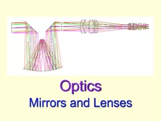
Concave and Convex Mirrors Concave and convex mirrors are curved mirrors similar to portions of a sphere. light rays light rays Concave mirrors reflect light from their inner surface, like the inside of a spoon. Convex mirrors reflect light from their outer surface, like the outside of a spoon.
Concave Mirrors • Concave mirrors are approximately spherical and have a principal axis that goes through the center, C, of the imagined sphere and ends at the point at the center of the mirror, A. The principal axis is perpendicular to the surface of the mirror at A. • CA is the radius of the sphere,or the radius of curvature of the mirror, R. • Halfway between C and A is the focal point of the mirror, F. This is the point where rays parallel to the principal axis will converge when reflected off the mirror. • The length of FA is the focal length, f. • The focal length is half of the radius of the sphere (proven on next slide).
To prove that the radius of curvature of a concave mirror is twice its focal length, first construct a tangent line at the point of incidence. The normal is perpendicular to the tangent and goes through the center, C. Here, i = r = .By alt. int. angles the angle at C is also ,andα= 2β. s is the arc length from the principle axis to the pt. of incidence. Now imagine a sphere centered at F with radius f. If the incident ray is close to the principle axis, the arc length of the new sphere is about the same ass. Froms = r, we haves = rβand s fα= 2fβ.Thus,rβ 2fβ, andr = 2f. r = 2f tangent line s • • f C F r
Focusing Light with Concave Mirrors Light rays parallel to the principal axis will be reflected through the focus (disregarding spherical aberration, explained on next slide.) In reverse, light rays passing through the focus will be reflected parallel to the principal axis, as in a flood light. Concave mirrors can form both real and virtual images, depending on where the object is located, as will be shown in upcoming slides.
• • C F Spherical Aberration F • • C Spherical Mirror Parabolic Mirror Only parallel rays close to the principal axis of a spherical mirror will converge at the focal point. Rays farther away will converge at a point closer to the mirror. The image formed by a large spherical mirror will be a disk, not a point. This is known as spherical aberration. Parabolic mirrors don’t have spherical aberration. They are used to focus rays from stars in a telescope. They can also be used in flashlights and headlights since a light source placed at their focal point will reflect light in parallel beams. However, perfectly parabolic mirrors are hard to make and slight errors could lead to spherical aberration. Continued…
Spherical vs. Parabolic Mirrors Parallel rays converge at the focal point of a spherical mirror only if they are close to the principal axis. The image formed in a large spherical mirror is a disk, not a point (spherical aberration). Parabolic mirrors have no spherical aberration. The mirror focuses all parallel rays at the focal point. That is why they are used in telescopes and light beams like flashlights and car headlights. SPHERICAL vs. PARABOLIC
image Concave Mirrors: Object beyond C The image formed when an object is placed beyond C is located between C and F. It is a real, inverted image that is smaller in size than the object. object • • C F Animation 1 Animation 2
image Concave Mirrors: Object between C and F The image formed when an object is placed between C and F is located beyond C. It is a real, inverted image that is larger in size than the object. object • • C F Animation 1 Animation 2
image Concave Mirrors: Object in front of F The image formed when an object is placed in front of F is located behind the mirror. It is a virtual, upright image that is larger in size than the object. It is virtual since it is formed only where light rays seem to be diverging from. object • • C F Animation
The image will be formed at C also, but it will be inverted. It will be real and the same size as the object. No image will be formed. All rays will reflect parallel to the principal axis and will never converge. The image is “at infinity.” Concave Mirrors: Object at C or F What happens when an object is placed at C? Animation What happens when an object is placed at F?
light rays Convex Mirrors • A convex mirror has the same basic properties as a concave mirror but its focus and center are located behind the mirror. • This means a convex mirror has a negative focal length (used later in the mirror equation). • Light rays reflected from convex mirrors always diverge, so only virtual images will be formed. • Rays parallel to the principal axis will reflect as if coming from the focus behind the mirror. • Rays approaching the mirror on a path toward F will reflect parallel to the principal axis.
Convex Mirror Diagram The image formed by a convex mirror no matter where the object is placed will be virtual, upright, and smaller than the object. As the object is moved closer to the mirror, the image will approach the size of the object. object image • • F C
s = s r do s di Mirror/Lens Equation Derivation From PCO, = + , so 2 = 2 + 2. From PCO, = 2 + , so - = -2 - . Adding equations yields 2 - = . P Froms = r, we haves = rβ, s diα,and s diα(for rays close to the principle axis). Thus: object s • T O C image di do (cont.)
Mirror/Lens Equation Derivation (cont.) From the last slide, = s/r, s/d0, s/di, and2β - = . Substituting into the last equation yields: P 2s s s - object = s r di do 2 1 1 • = + r T O di do C image 1 1 2 = + 2f di do di 1 1 1 = + f di do do The last equation applies to convex and concave mirrors, as well as to lenses, provided a sign convention is adhered to.