A C ompact Video M icroscope I maging S ystem With Intelligent Controls ( CMIS )
A C ompact Video M icroscope I maging S ystem With Intelligent Controls ( CMIS ) S tereo I maging V elocimetry US Patent # 5,905,568 - Stereo imaging velocimetry (1999) US Patent # 6,603,535 - Stereo imaging velocimetry system and method (2003)

A C ompact Video M icroscope I maging S ystem With Intelligent Controls ( CMIS )
E N D
Presentation Transcript
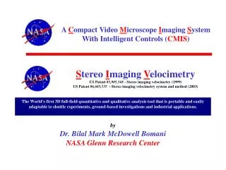
A Compact Video Microscope Imaging System With Intelligent Controls (CMIS) StereoImagingVelocimetryUS Patent #5,905,568 - Stereo imaging velocimetry (1999) US Patent #6,603,535 - Stereo imaging velocimetry system and method (2003) The World's first 3D full-field quantitative and qualitative analysis tool that is portable and easily adaptable to shuttle experiments, ground-based investigations and industrial applications. byDr. Bilal Mark McDowell Bomani NASA Glenn Research Center
A Compact Video Microscope Imaging System With Intelligent Controls (CMIS)
Downlink Uplink Communications Link
10”x1.5”x1.5” 1/2” color CCD 768x494 pixels up to 3X mag 11.5”x2”x2” 1/2” color CCD 768x494 pixels up to 70X mag 12”x24”x12” Zeiss Conventional Microscope
Intelligent Algorithms Instrumentation and Control Systems Machine Vision / Image Processing Customization!!! Customization!!! Hardware and Software Integration Web-Enabled Technologies Intelligent Graphical User Interface
CMIS is a miniature machine vision system, which combines intelligent image processing with remote control capabilities. The software also has a user-friendly interface, which can be used independently of the hardware for further post-experiment analysis.
Auto-Focus Capabilities Out-of-Focus Image FFT of Out-of-Focus Image In-Focus Image FFT of In-Focus Image
CMISPotential Uses and Applications • Microscopy – Interface Detection and Tracking Bio-Medical – Cell Labeling & Tracking • Bio-Medical – Cell Detection and Feature ExtractionIn-Line Process Inspection – Surface Identification • Web-Enabling Technologies – Remote CMIS
Bio-Medical – Cell Labeling & Tracking Identify Each Individual Sphere
Bio-Medical – Cell Labeling & Tracking Label Each Sphere as Full or Partial
Bio-Medical – Cell Labeling & Tracking Determine Sphere Displacements in Original Image
Bio-Medical – Cell Labeling & Tracking # Number of noise particles (< 3 pixels): 396# Number of small particles (< 50 pixels): 171# Closest to center: 4
Bio-Medical – Cell Detection and Feature Extraction Case #1 Metrics
Bio-Medical – Cell Detection and Feature Extraction Case #2 Metrics
In-Line Process Inspection – Surface Identification Ideal Surface Template Defect Case #1 Defect Case #2
In-Line Process Inspection – Surface Identification Ideal Surface Template Defect Case #1 Defect Case #2
Year 2000Imaging Solution of the Year!!!from • Advanced Imaging Magazine: • Medical Imaging, Bioscience, and Scientific Analysis • NASA CMIS Research Team: • Dr. Mark McDowell • Elizabeth Gray • Rick Rogers • Stephanie Grasson • (Glenn Research Center, Cleveland Ohio)
StereoImagingVelocimetry The World's first 3D full-field quantitative and qualitative analysis tool that is portable and easily adaptable to shuttle experiments, ground-based investigations and industrial applications. US Patent #5,905,568 - Stereo Imaging Velocimetry (1999) US Patent #6,603,535 - Stereo Imaging Velocimetry system and method (2003)
Stereo Imaging VelocimetryGoals and ObjectivesStudy low velocity fluid/air flow problemsProduce 3D quantitative data from experimentsSIV applications package - PC Based Stereo Imaging Velocimetry is a system used to track the motion of particles in a transparent liquid in three dimensions. SIV consists of two cameras, oriented at 90o with respect to each other, observing a fluid experiment which has been seeded with small tracer particles. Each camera will record two dimensional data of the motion of the seed particles in the observation volume. Three dimensional data is obtained by computationally combining the two dimensional information.
Stereo Imaging Velocimetry The two cameras are set up perpendicular to each other, so that two widely disparate views are recorded. The two views are computationally combined to obtain three dimensional coordinates of the seed particles.
SIV Benefits and Potential Uses • Benefits: • Provides accurate, reproducible quantitative flow measurements • Three Dimensional • Uses No Lasers • Safe and Affordable • Utilizes "off-the-shelf" CCD cameras and PC workstation hardware • Unique tool for direct comparison of computed and experimentally measured fluid flows • No limitation on fluid flow scale to be measured (microscopic to macroscopic) • Velocities directly comparable to computational models • Potential Uses: • Combustion intake, compression, expansion, exhaust studies • Air flow studies around buildings • Improved aerodynamics of automobiles and aircraft • Avoiding "no flow" regions in artificial hearts • Analysis of crash dummy motion • Modeling of continuous casting operations (steel, nonferrous alloys) • Quieter airflow within auto heating & cooling ducts • More efficient HVAC
SIV Nomenclature Right camera perspective (the left camera perspective is analogous) xi yi zi = Absolute x y z coordinates of particle i. XRi ZRi = Window coordinates of particle i on the face of the chamber. xRi zRi = Pixel coordinates of particle i as seen by the right camera. fR = Effective focal length of the right camera. DR = Effective distance between the right camera and the face of the chamber. dR = Horizontal distance of the right camera axis from the origin. R = Vertical distance of the right camera axis from the origin. CR = Camera dependent constant with the units mm/pixel.
SIV Consists of Five Main Phases: 1) Camera Calibration 2) Centroid Determination with Overlap Decomposition 3) Particle Tracking 4) Stereo Matching 5) 3D Analysis
SIV 3D Vectors Top View Side View
Structure Of Flame Balls At Low Lewis-number (SOFBALL) SIV has been used for three Space Shuttle missions, providing analysis for the Combustion Module 1 (STS-83 and STS-94) and Combustion Module-2 experiments (STS-107 – Columbia) on a the SOFBALL (Structure Of Flame Balls At Low Lewis-number) project. SIV was used for over 50 Combustion Module experiments analyzing and identifying the 3D positions of flameball data.
MOBI experiment SIV is currently being used to identify and track the motion of bubble droplet formations in a viscous fluid. The results will be used to improve the understanding of multiphase flows relevant to oil wells, bubble segregation in bioreactors and effect on oxygen transport to cultivated cells.
NCharge The primary goal of this effort is to develop a technique that allows measurement of the electrostatic (or coulombic) charge on individual grains of material with diameters in the range of 50 to 500 microns by utilizing a microgravity environment.
Space Act Agreement with LTV Steel Funded by TU Office · Provide a diagnostic tool for quantitative and qualitative characterization of fluid flows. · Permit direct comparison between computed and experimentally measured 3-D flows. · Provide vector maps of the mold flow. · Provide verification for mathematical models. · PC-based SIV applications package, available for incorporation into fluid experiments. · Help develop new nozzle designs to reduce defects. Raw Data Continuous Casting Model SIV Vectors Continuous Casting Model
Space Act Agreement with Kirby Vacuum Cleaner Company • Investigating the brush roll design for the next generation Kirby model. • Producing 3D velocity vectors of air flow studies. • Must use high speed video equipment.
A Compact Video Microscope Imaging System With Intelligent Controls (CMIS) StereoImagingVelocimetryUS Patent #5,905,568 - Stereo imaging velocimetry (1999) US Patent #6,603,535 - Stereo imaging velocimetry system and method (2003) The World's first 3D full-field quantitative and qualitative analysis tool that is portable and easily adaptable to shuttle experiments, ground-based investigations and industrial applications. byDr. Bilal Mark McDowell Bomani NASA Glenn Research Center