Download

1 / 21
210 likes | 229 Vues
Designing a temperature controller to automate paint curing on automobiles using infrared lamps to vary surface temperature, enhancing efficiency and accuracy. The system includes a microprocessor-based controller that regulates lamps based on sensor input, adjusting temperature for different curing stages and shutting off when the process is complete.

E N D
Dec01-11 Team Members Michael Burman, CprE Jonathan Johnson, EE Matthew McMullen, CprE Tom Vedder, EE Mark Wibholm, EE Project Faculty Advisors Dr. John Lamont Dr. Ralph Patterson Project Client H&S Autoshot Centerville, IA Temperature Controller for Infrared Paint CuringSeptember 13, 2001
Problem Statement Design Objectives Operating Environment End-Product Description Assumptions Limitations Project Risks and Concerns Technical Approach Evaluation of Project Success Recommendations for Further Work Human Budget Financial Budget Lessons Learned Closing Summary Questions? Presentation Outline
Problem Statement Design a temperature controller to automate paint curing on automobiles using infrared lamps. The lamps must vary the surface temperature throughout the curing process. The sensor must operate without contacting the surface.
Design Objectives Functionality of Temperature Controller • Sets infrared lamps to various specified temperatures • Holds temperature of curing surface for specified amount of drying time • Applies two stages of heating • Shuts off lamps when drying cycle is finished Design Constraints • Device must be small enough to mount on lamp stands • Paint surface cannot be touched • Paint types require various curing times and temperatures
Design Objectives (cont.) Intended Users • Auto body repair technicians and mechanics Intended Use • Automate paint curing process Intended Advantages • Reduce drying time from 2 days to 15 minutes • Increase production and efficiency of vehicle painting • Increase accuracy of curing process
Operating Environment • Temperatures may range from above 150° F to below freezing temperatures when stored • High amounts of dust and other contaminants especially solvents • Device may be knocked around or tipped over
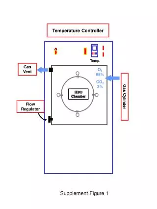
End-Product Description A microprocessor-based temperature controller that automates the automobile paint curing process by: • Regulating infrared lamps • Receiving input from a non-contact sensor that reads the surface temperature • Using an internal timer to alter the temperature for various curing stages • Ending the curing process by switching off the lamps
End-Product Description (cont.) Temperature sensor detects room temperature Upper level temperature has been reached Upper level temperature is set to 90 degrees Fahrenheit
Assumptions • Temperature controller will display the temperature of the surface • Temperature sensor will be accurate within ±2° Fahrenheit • Curing lamp will provide uniform temperature coverage over the entire curing surface (maximum 2 feet in one direction) • Curing lamps will not directly affect infrared temperature sensor readings of the paint surface • Limited electrical technology knowledge of users implies that the device should be simple to operate
Limitations • Paint surface cannot be touched to detect temperature • Device must be mobile • Temperature sensors and controllers may be very expensive • Project completion time is limited • Temperature sensor accuracy decreases as distance from the surface increases
Project Risks and Concerns • Unfamiliar technology • Loss of a critical person may occur • Testing the finished product may be difficult due to location • Time to complete the project is limited
Technical Approach • Utilize infrared temperature sensor to read surface temperature • Utilize the temperature controller to select, set, and control parameters of the process • Utilize temperature controller to regulate lamp temperature • Continue to read and adjust surface temperature until curing is complete
Evaluation of Project Success 1st Semester Milestones • Project Plan (Fully Met) • Project Poster (Fully Met) • Design Report (Fully Met) • Select temperature controller (Partially Met) • Select non-contact infrared temperature sensor (Fully Met) • Learn how to use temperature controller and how to program it (Fully Met)
Evaluation of Project Success (cont.) 2nd Semester Milestones • System Implementation (Partially Met) • Test paint curing system (Partially Met) • Complete all project documentation (Partially Met) • Final Report (Not Started) • Present project (Not Started)
Recommendations for Future Work • Utilize an advanced temperature controller with large amounts of memory to store curing times for many different paints • Ability to control more than one bank of lights simultaneously
Lessons Learned • Methods used in the paint curing industry • How to program a temperature controller • How infrared temperature sensors work • Meet at least once a week with group members • Contact advisors and professors for advice and feedback • You can plug wires into the wall and have it work • When someone says “Alright guys stand back,” take them seriously
Closing Summary The finished system will: • Automate paint drying process • Increase productivity, efficiency, and accuracy of paint drying process • Decrease drying time from 2 days to 15 minutes