Download

1 / 27
270 likes | 484 Vues
Lesson 25 AC Power and Power Triangle. Learning Objectives. Define real (active) power, reactive power, average, and apparent power. Calculate the real, reactive, and apparent power in AC series parallel networks.

E N D
Learning Objectives • Define real (active) power, reactive power, average, and apparent power. • Calculate the real, reactive, and apparent power in AC series parallel networks. • Graph the real and reactive power of purely resistive, inductive, or capacitive loads in AC series parallel networks as a function of time. • Determine when power is dissipated, stored, or released in purely resistive, inductive, or capacitive loads in AC series parallel networks. • Use the power triangle determine relationships between real, reactive and apparent power.
AC Power AC Impedance is a complex quantity made up of real resistance and imaginary reactance. AC Apparent Power is a complex quantity made up of real active power and imaginary reactive power:
AC Real (Active) Power (P) The Active power is the power that is dissipated in the resistance of the load. It uses the same formula used for DC (V & I are the magnitudes, not the phasors): WARNING! #1 mistake with AC power calculations! The Voltage in the above equation is the Voltage drop across the resistor, not across the entire circuit! CAUTION! REAL value of resistance (R) is used in REAL power calculations, not IMPEDANCE (Z)!
AC Imaginary (Reactive) Power (Q) The reactive power is the power that is exchanged between reactive components (inductors and capacitors) The formulas look similar to those used by the active power, but use reactance instead of resistances. Units: Volts-Amps-Reactive (VAR) Q is negative for a capacitor by convention and positive for inductor. Just like X is negative for a capacitor! (-Xcj) WARNING! #1 mistake with AC power calculations! The Voltage in the above equation is the Voltage drop across the reactance, not across the entire circuit!
AC Apparent Power (S) The apparent power is the power that is “appears” to flow to the load. The magnitude of apparent power can be calculated using similar formulas to those for active or reactive power: Units: Volts-Amps (VA) V & I are the magnitudes, not the phasors
AC Power Notice the relationship between Z and S: Real power calculated with R Reactive power calculated with X Apparent power calculated with Z
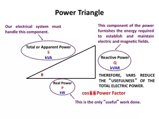
Power Triangle The power triangle graphically shows the relationship between real (P), reactive (Q) and apparent power (S).
Example Problem 1 Determine the real and reactive power of each component. Determine the apparent power delivered by the source.
Real and Reactive Power The power triangle also shows that we can find real (P) and reactive (Q) power. NOTE: The impedance angle and the “power factor angle” are the same value!
Example Problem 2 Determine the apparent power, total real and reactive power using the following equations:
Total Power in AC Circuits The total power real (PT) and reactive power (QT) is simply the sum of the real and reactive power for each individual circuit elements. How elements are connected does not matter for computation of total power.
Total Power in AC Circuits Sometimes it is useful to redraw the circuit to symbolically express the real and reactive power loads
Example Problem 3 Determine the unknown real (P2) and reactive powers (Q3) in the circuit below. Determine total apparent power Draw the power triangle Is the unknown element in Load #3 an inductor or capacitor?
Example Problem 4 Determine the value of R, PT and QT Draw the power triangle and determine S.
WARNING…Proofs for Real and reactive Power calculations follow…
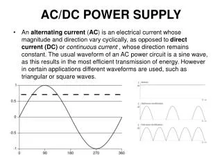
AC Power to a Resistive Load • In ac circuits, voltage and current are functions of time. • Power at a particular instant in time is given This is called instantaneous power.
Average Power to a Resistive Load • p is always positive • All of the power delivered by the source is absorbed by the load. • Average power P = VmIm/2
Average Power to a Resistive Load • Using RMS values V and I • Active power is the average value of instantaneous power.
Consider the following circuit where i = Imsin t . Can we write an expression instantaneous power or pL(t) ? Power to an Inductive Load
p is equally positive and negative. All of the power delivered by the source is returned. Average power PL = 0 W Power to an Inductive Load
Reactive Power • Reactive power is the portion of power that flows into load and then back out. • It contributes nothing to average power. • The power that flows into and out of a pure inductor is reactive power only.
Consider the following circuit where i = Imsin t . Can we write an expression instantaneous power or pC(t) ? Power to a Capacitive Load
p is equally positive and negative All of the power delivered by the source is returned (no power losses with a pure reactive load). Average power PC = 0 W Power to a Capacitive Load
AC Power to a Resistive LoadAC Power to a Inductive LoadAC Power to a Capacitive Load