Download
1 / 9
90 likes | 203 Vues
Learn about digital systems, binary codes, parity bits, and various number systems like decimal, binary, hexadecimal in this detailed summary.

E N D
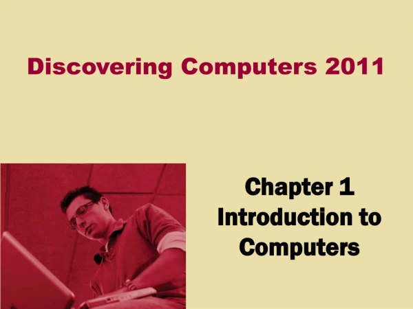
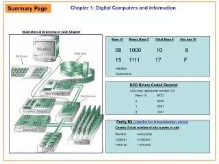
Chapter 1: Digital Computers and Information Summary Page Illustration at beginning of each Chapter Base 10Binary Base 2Octal Base 8 Hex bas 16 08 1000 10 8 15 1111 17 F -Addition -Subtraction BCD Binary Coded Decimal 4 bit code represents number 0-9 Base 10 BCD 0 0000 1 0001 9 1001 Parity Bit (checks for transmission errors Checks if total number of bits is even or odd Number even parity 1000001 01000001 1010100 11010100
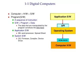
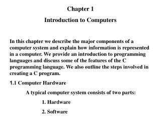
Digital ComputersChapter 1: Characteristics of a digital system is the manipulation of discrete elements of information. Any set that is restricted to a finite number of elements contains discrete information. Examples of discrete sets are the 10 decimal digits, the 26 letters of the alphabet etc. Discrete elements of information are represented in a digital system by physical quantities called signals. Electrical signals such as voltages and currents are most common. Transistors dominate the circuitry that implements these signals. Signals in most present day electronic digitals systems ase just two discrete values and are therefore said to be binary. Logic Design deals with the basic concepts and tools used to design digital hardware consisting of logic circuits. Computer Design deals with the additional concepts and tools used to design computers and other complex digital hardware. Computers and digital hardware in general are referred to as digital systems. Orange Boxes include information not in your text A Bipolar Transistor is a 3 terminal semiconductor sevice in which a small current at one terminal can control a much larger current flowing between the 2nd and 3rd terminal. Transistors can function both as amplifiers ans switches. And Gate +5V +5V +5V A B Out 10K R2 1K A Hi R1 1K +5V 10K S1 LED Lo Off Hi On LED B +5V Lo Out +5V +5V +5V 4.7K
Digital ComputersChapter 1: We typically represent two discrete values by ranges of voltages values called HIGH and LOW. The HIGH output voltage value ranges between 4.0 and 5.5 Volts The LOW output voltages ranges between -0.5 and 5.5 voltages The HIGH input range allows 3.0-5.5 volts to be recognized The LOW input ranges allow -0.5 to 2.0 volts. The fact that the input ranges are longer than the output ranges allows the circuits to function correctly in spite of variation in their behavior and undesirable noise voltages that may be added or subtracted from their outputs. Output INPUT HIGH (H) or True (T) or 1 5.0 HIGH 4.0 3.0 2.0 1.0 LOW (L) or False (F) or 0 0.0 LOW Parity Bits:Used to detect errors (if there is excessive noise or errors, how would you detect it?) An additional bit is sometimes added to a binary code to make the total number of 1’s in the resulting code word even or odd. Original message(7 bits) Modified with Even Parity (8 Total bits) 1000001 (two 1’s) 01000001 (total # bits is even no change) 1010100 (three 1’s) 11010100 (total # bits is odd, so add a 1 so total is even four 1’s)
Digital ComputersChapter 1: Why is Binary used? Consider a system with 10 values. The voltages between 0 and 5.0 volts would be divided into 10 ranges. Each of length 0.5 volt. A circuit with have to provide an output with each of these ranges. An input circuit would have to determine which of these belonged to each of these 10 ranges. If we wanted to compensate for noise that each range would be 0.25 volts. And the boundaries would be less than 0.25 volts This would require costly and complex electronic circuits and still would be disturbed by small noise voltages. Instead binary circuits are used with significant variation in output and input ranges. The resulting transistor circuit is simple, easy to design and extremely reliable. Information Representation: A Binary Digit is referred to as a bit. Information is represented as groups of bits. By using various coding schemes groups of bits can represent discrete symbols. American Standard Code for Information Interchange (7-bit code) (pg 25 text) 0000 0001 0010 0011 0100 0101 0110
Digital ComputersChapter 1: Codes Unicode: A 16 bit code for representing the symbols and ideographs for the worlds languages. Gray Code: A code having the property that only one bit at a time changes between codes during counting is a Gray Code. Binary Coded Decimal: (BCD) Most commonly used code to represent decimal digits: (binary combinations 1010-1111 not used) • DecimalBCD • 0 0000 • 0001 • 0010 • 0011 • 0100 • 0101 • 0110 • 0111 • 1000 • 1001
Digital ComputersChapter 1: Number Systems Octal: (base 8) Use symbols 0,1,2,3,4,5,6,7 83 82 81 80 Hexadecimal: (base 16): Use symbols0,1,2,3,4,5,6,7,8,9,A,B,C,D,E,F 163 162 161 160 Decimal: (base 10) Use symbols 0,1,2,3,4,5,6,7,8,9 104 103 102 100 • Base 10 Base 2 Base 8 Base 16 • 1018 42 1 64 8 1 256 16 1 • 102101100232221208281 80163 161 160 • 1 0 0 0 1 0 0 1 0 0 1 • 1010 10 0 12 0 0 A Value Power Example 2: Base 10Base 2 100 101 32 168 421 Carries 1 0 1 1 0 0 2 21011 0 + 23 +1 0111 ------- ------------- 4 5 1 0 1 1 0 1 Arithmetic Operations: Example 1: Base 10Base 2 100 101168 4 2 1 Carries 0 0 0 0 0 1 2 0 11 0 0 + 17 +1 0 0 0 1 ------- ------------- 2 9 111 0 1 Power 10
Digital ComputersChapter 1: Number Systems The Rules for subtraction are the same in decimal. A borrow here adds 2 (in the decimal system a borrow adds 10) Example: (Base 10) 1 13 15 245 -1 - 9 7 - 197 ---- ---- ---- ------- 4 8 48 Borrow 1 1 Explanation Example 1: Base 10Base 2 100 101168 4 2 1 Borrows 0 0 1 1 0 2 2 1 01 1 0 - 19 -1 0 0 1 1 ------- ------------- 0 3 000 1 1 Column 3 0 - 1 But we needed to borrow due to the second column, so 10 borrow 1 = 1 1 -1 ---- 0 Column 1 0 - 1 Cant take 1 from 0 so we borrow from the next column becomes 10 - 1 ------ 1 Column 2 1 - 1 This would normally be 0 (1-1) But we needed to borrow due to the first column, so 11 borrow 1 = 10 10 -1 ---- 1 Starting Problem Column 1 Power 10 Result
Digital ComputersChapter 1: Number Systems Two’s Complement: (used to subtract two numbers by adding) (Hardware simpler) Subtract a number by converting the subtrahend to a two complement form then adding. Take the boolean complement of each bit, including the sign bit. -That is set each 1 to 0 and each 0 to 1. Then add 1 B Register 18=00010010 B Register 25=00011001 Example: 25 00011001 -18 00010010 2s compliment Result positive Complementer 11101110 2s compliment 00011001 + 11101110 --------------- 7=100000111 adder +18 = 00010010 Reverse the digits 11101101 Then add 1 +1 ------------- 11101110 = -18 Overflow ignored Example: 18 00010010 00010010 11111001 -25 00011001 2s complement 11100111 + 11100111 reverse digits 00000110 -------------- +1 011111001 Final answer 00000111 =-7 Have to reverse process