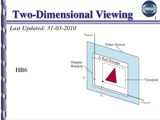
Viewing & Clipping In 2D
Viewing & Clipping In 2D. Contents. Windowing Concepts Clipping Introduction Brute Force Cohen-Sutherland Clipping Algorithm Area Clipping Sutherland-Hodgman Area Clipping Algorithm. Windowing I. A scene is made up of a collection of objects specified in world coordinates.

Viewing & Clipping In 2D
E N D
Presentation Transcript
Contents • Windowing Concepts • Clipping • Introduction • Brute Force • Cohen-Sutherland Clipping Algorithm • Area Clipping • Sutherland-Hodgman Area Clipping Algorithm
Windowing I • A scene is made up of a collection of objects specified in world coordinates World Coordinates
Windowing II • When we display a scene only those objects within a particular window are displayed Window wymax wymin wxmax wxmin World Coordinates
Windowing III • Because drawing things to a display takes time we clip everything outside the window Window wymax wymin wxmax wxmin World Coordinates
Clipping • For the image below consider which lines and points should be kept and which ones should be clipped P4 Window P2 wymax P6 P3 P1 P5 P7 P9 P8 wymin P10 wxmin wxmax
Point Clipping • Easy - a point (x,y) is not clipped if: • wxmin ≤ x ≤ wxmax AND wymin ≤ y ≤ wymax • otherwise it is clipped P4 Clipped Clipped Window P2 wymax Clipped P5 P1 P7 Points Within the Window are Not Clipped P9 P8 wymin P10 Clipped wxmin wxmax
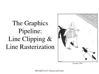
Line Clipping • Harder - examine the end-points of each line to see if they are in the window or not
Brute Force Line Clipping • Brute force line clipping can be performed as follows: • Don’t clip lines with both end-points within the window • For lines with one end-point inside the window and one end-point outside, calculate the intersection point (using the equation of the line) and clip from this point out
Brute Force Line Clipping (cont…) • For lines with both end-points outside the window test the line for intersection with all of the window boundaries, and clip appropriately • However, calculating line intersections is computationally expensive • Because a scene can contain so many lines, the brute force approach to clipping is much too slow
Cohen-Sutherland Clipping Algorithm • An efficient line clipping algorithm • The key advantage of the algorithm is that it vastly reduces the number of line intersections that must be calculated Dr. Ivan E. Sutherland co-developed the Cohen-Sutherland clipping algorithm. Sutherland is a graphics giant and includes amongst his achievements the invention of the head mounted display. Cohen is something of a mystery – can anybody find out who he was?
Cohen-Sutherland Clipping Algorithm • One of the earliest algorithms with many variations in use. • Processing time reduced by performing more test before proceeding to the intersection calculation. • Initially, every line endpoint is assigned a four digit binary value called a region code, and each bit is used to indicate whether the point is inside or outside one of the clipping-window boundaries.
Cohen-Sutherland Clipping Algorithm 4 3 2 1 Top Bottom Right Left • We can reference the window edges in any order, and here is one possibility. • For this ordering, (bit 1) references the left boundary, and (bit 4) references the top one. • A value of 1 (true) in any bit position indicate that the endpoint is outsides of that border. • A value of 0 (false) indicates that the endpoint is inside or on that border.
Cohen-Sutherland: World Division • The four window borders create nine regions • The Figure below lists the value for the binary code in each of these regions. Thus, an endpoint that is below and to the left of the clipping window is assigned the region (0101). The region code for any endpoint inside the clipping window is (0000).
Cohen-Sutherland: Labelling P11 [1010] P4 [1000] Window wymax P6 [0000] P3 [0001] P12 [0010] P5 [0000] P7 [0001] P9 [0000] P8 [0010] wymin P10 [0100] P13 [0101] P14 [0110] wxmin wxmax • Every end-point is labelled with the appropriate region code
Cohen-Sutherland: Lines In The Window P11 [1010] P4 [1000] Window wymax P6 [0000] P3 [0001] P12 [0010] P5 [0000] P7 [0001] P9 [0000] P8 [0010] wymin P10 [0100] P13 [0101] P14 [0110] wxmin wxmax • Lines completely contained within the window boundaries have region code [0000] for both end-points so are not clipped
Cohen-Sutherland: Lines Outside The Window P11 [1010] P4 [1000] Window wymax P6 [0000] P3 [0001] P12 [0010] P5 [0000] P7 [0001] P9 [0000] P8 [0010] wymin P10 [0100] P13 [0101] P14 [0110] wxmin wxmax • Any lines with 1 in the same bit position for both end-points is completely outside and must be clipped. • For example a line with 1010 code for one endpoint and 0010 for the other (line P11, P12) is completely to the right of the clipping window.
Cohen-Sutherland: Inside/Outside Lines • We can perform inside/outside test for lines using logical operators. • When the or operation between two endpoint codes is false (0000), the line is inside the clipping window, and we save it. • When the and operation between two endpoint codes is true (not 0000), the line is completely outside the clipping window, and we can eliminate it.
Cohen-Sutherland: Other Lines • Lines that cannot be identified as completely inside or outside the window may or may not cross the window interior • These lines are processed as follows: • Compare an end-point outside the window to a boundary (choose any order in which to consider boundaries e.g. left, right, bottom, top) and determine how much can be discarded • If the remainder of the line is entirely inside or outside the window, retain it or clip it respectively
Cohen-Sutherland: Other Lines (cont…) • Otherwise, compare the remainder of the line against the other window boundaries • Continue until the line is either discarded or a segment inside the window is found • We can use the region codes to determine which window boundaries should be considered for intersection • To check if a line crosses a particular boundary we compare the appropriate bits in the region codes of its end-points • If one of these is a 1 and the other is a 0 then the line crosses the boundary
Cohen-Sutherland Examples Window wymax P9 [0000] P9 [0000] wymin P10’ [0000] P10 [0100] wxmin wxmax • Consider the line P9 to P10 below • Start at P10 • From the region codes of the two end-points we know the line doesn’t cross the left or right boundary • Calculate the intersection of the line with the bottom boundary to generate point P10’ • The line P9 to P10’ is completely inside the window so is retained
Cohen-Sutherland Examples (cont…) P4 [1000] P4’ [1001] Window wymax P3 [0001] P3 [0001] wymin wxmin wxmax • Consider the line P3 to P4 below • Start at P4 • From the region codes of the two end-points we know the line crosses the left boundary so calculate the intersection point to generate P4’ • The line P3 to P4’ is completely outside the window so is clipped
Cohen-Sutherland Examples (cont…) Window wymax P7’ [0000] P8 [0010] P7 [0001] P8’ [0000] wymin wxmin wxmax • Consider the line P7 to P8 below • Start at P7 • From the two region codes of the two end-points we know the line crosses the left boundary so calculate the intersection point to generate P7’
Cohen-Sutherland Examples (cont…) Window wymax P7’ [0000] P8 [0010] P7 [0001] P8’ [0000] wymin wxmin wxmax • Consider the line P7’ to P8 • Start at P8 • Calculate the intersection with the right boundary to generate P8’ • P7’ to P8’ is inside the window so is retained
Cohen-Sutherland Worked Example Window wymax wymin wxmax wxmin
Calculating Line Intersections • Intersection points with the window boundaries are calculated using the line-equation parameters • Consider a line with the end-points (x1, y1) and (x2, y2) • The y-coordinate of an intersection with a vertical window boundary can be calculated using: y = y1 + m (xboundary - x1) where xboundary can be set to either wxmin or wxmax
Calculating Line Intersections (cont…) • The x-coordinate of an intersection with a horizontal window boundary can be calculated using: x = x1 + (yboundary - y1)/ m where yboundary can be set to either wymin or wymax • m is the slope of the line in question and can be calculated as m = (y2 - y1) / (x2 - x1)
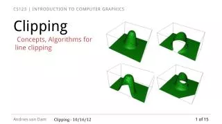
Area Clipping • Similarly to lines, areas must be clipped to a window boundary • Consideration must be taken as to which portions of the area must be clipped
Sutherland-Hodgeman Polygon Clipping • Example Start at the left boundary 1,2 (out,out) → clip 2,3 (in,out) → save 1’, 3 3,4 (in,in) → save 4 4,5 (in,in) → save 5 5,6 (in,out) → save 5’ Saved points → 1’,3,4,5,5’ 6,1 (out,out) → clip Using these points we repeat the process for the next boundary.
Weiler-Atherton Polygon Clipping • Convex polygons are correctly clipped by the Sutherland-Hodgeman algorithm, but concave polygons may be displayed with extra areas (area inside the red circle), as demonstrated in the following figure.
Weiler-Atherton Polygon Clipping • This occurs when the clipped polygon should have two or more separate sections. But since there is only one output vertex list, the last vertex in the list is always joined to the first vertex. • There are several things we could do to correctly display concave polygons. • For one, we could split the concave polygon into two or more convex polygons and process each convex polygon separately • Another possibility is to modify the Sutherland-Hodgeman approach to check the final vertex list for multiple vertex points along any Clip window boundary and correctly join pairs of vertices. • Finally, we could use a more general polygon clipper, such as either the Weiler-Atherton algorithm or the Weiler algorithm.
Weiler-Atherton Polygon Clipping • In Weiler-Atherton Polygon Clipping, the vertex-processing procedures for window boundaries are modified so that concave polygons are displayed correctly. • This clipping procedure was developed as a method for identifying visible surfaces, and so it can be applied with arbitrary polygon-clipping regions.
Weiler-Atherton Polygon Clipping • The basic idea in this algorithm is that instead of always proceeding around the polygon edges as vertices are processed, we sometimes want to follow the window boundaries. • Which path we follow depends on the polygon-processing direction (clockwise or counterclockwise) and whether the pair of polygon vertices currently being processed represents an outside-to-inside pair or an inside-to-outside pair.
Weiler-Atherton Polygon Clipping • For clockwise processing of polygon vertices, we use the following rules: • For an outside-to-inside pair of vertices, follow the polygon boundary • For an inside-to-outside pair of vertices, follow the window boundary in a clockwise direction.
Weiler-Atherton Polygon Clipping • Example • In the following figure, the processing direction in the Weiler-Atherton algorithm and the resulting clipped polygon is shown for a rectangular clipping window.