Capacitive Touch
Capacitive Touch. Time to replace that old mechanical button! - Christopher Semanson, Functional Safety Systems Manager Automotive Power Management Christopher.Semanson@renesas.com. About your presenter. Education: University Of Michigan @ Dearborn

Capacitive Touch
E N D
Presentation Transcript
Capacitive Touch Time to replace that old mechanical button! - Christopher Semanson, Functional Safety Systems Manager Automotive Power Management Christopher.Semanson@renesas.com
About your presenter • Education: University Of Michigan @ Dearborn • Bachelor's of Science in Electrical and Computer Engineering • Master’s of science in Electrical Engineering • Thesis topic was Creation of an Undergraduate Laboratory Curriculum in EMC • Employment: • Ford (Dearborn, MI): • 6 Years: • Designing Embedded Controls for Low Voltage and other Vehicle Systems and systems engineer for Driver Assistance Technologies. • Renesas (Durham, NC): • 4 Years: • Working on non-Automotive Electrical Applications for embedded Systems and focusing on Analog Electronics support. • Functional Safety Systems Manager for Power Management Devices using ISO26262. • University Of Michigan Dearborn (Dearborn, MI): • 7 Years Leading the Laboratory Section of the Electromagnetic Compatibility Class (ECE319).
Agenda What is capacitive touch? And why is it something we care about? What makes up a capacitive touch system? Routing and Stackup in a capacitive touch system. Sources of noise in a system (both traditional and non-traditional) Examples
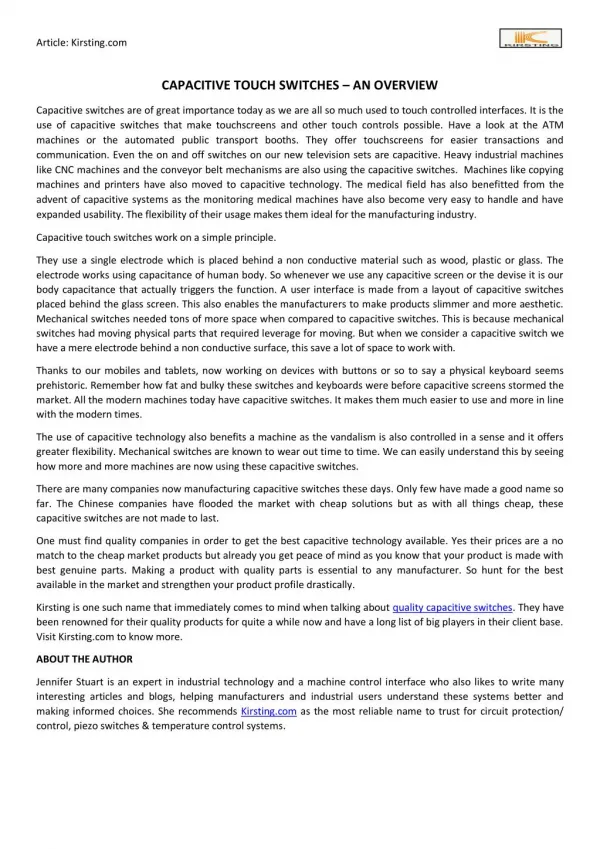
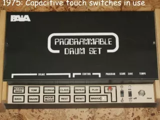
Why capacitive touch? • Electrical switches have been around since the beginning of time. • Enter capacitive touch as a means to both save money in manufacturing an assembly cost.
Functioning Principles • How does capacitive touch work? • Measurement methods can vary between manufacturers but the physics remain the same: • By sending a specialized measurement signal to a printed circuit board pattern the measurement device creates an electrostatic field which your finger then interacts with.
The Overview of a Capacitive Touch System The dielectric covering is usually Lexan, glass, or some sort of plastic. Used to insulate the finger from the sensor. Too thick influences sensitivity, too thin makes it too sensitive. (Usually 2-5mm, upto ~10mm) The MCU or ASIC has a specialized peripheral that measures the capacitance of the sensor circuit. The pad design determines how the electrostatic field is contained in the sensing circuit, it is influenced by the stack up and how close it is to a return plane. The routing and stackup determines how much parasitic capacitive load there is in the sensing circuit. The basics of a capacitive touch system
Introducing: Self-Capacitive Touch • The first flavor of capacitive touch we will discuss is Self-Capacitive Touch: • Single ended measurement. • Measures the increase in capacitance from a human interaction. • Great sensitivity, not so great robustness to environmental factors. • Easy to implement.
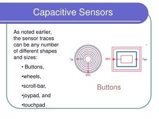
Self-Capacitive Touch Patterns Pad construction is usually limited in size. Pad construction usually has some sort of cutout allowing an indicator or something to show through, indicating touch.
Introducing: Mutual Capacitance • The second flavor of capacitive touch we will discuss is Mutual-Capacitive Touch: • Two single ended measures which the hardware block then combines.. • Measures the decrease in capacitance from a human interaction. • Less sensitive, great robustness to environmental factors. • More complex patterns.
Mutual Capacitance Patterns • Mutual capacitance creates the field between the two ends of the pads and their surroundings, as well as between the plates. • Each manufacturer specifies what kind of sensor pattern to use.
Designing with capacitive Touch (Parasitic, Routing and Stackup)
Parasitic Capacitance • As previously stated, the sensitivity to a human is key in creating a robust user interface. • This is all based on parasitic capacitance, which is something that hardware engineers are all too familiar with as it contributes to. • Signal integrity issues. • Crosstalk issues. • Thus to increase the human body to parasitic ratio we must consider copper surrounding the pad and trace.
Parasitic Capacitance • What are the two major factors that impact the parasitic capacitance that the system senses? • Routing • Stackup • Traces and sensor pads all carry with it some parasitic capacitance in a per unit length or size.
Quantitate Look at Parasitic Capacitance • Approach routing in two different ways, qualitatively and quantitatively. • Quantitatively we can determine the capacitance per unit length based on trace length, distance above a plane and distance to neighboring traces.
Quantitative Look At Parasitic Capacitance • Qualitatively we can state that the neighboring copper’s potential has impacts the measurement as well. • The potential of the neighboring trace, especially if it changes will influence the measurement.
Quantitative Look At Parasitic Capacitance LED Traces Mutual Touch Traces
PCB Stackup • Stackup is another major way designers can influence the sensitivity of the system. • Too much copper under the sensors will impact the sensitivity of the system. • Too little copper will increase your risk for conducted immunity testing (IEC61000-4-6), similar to BCI.
Sources of Noise (Both traditional and non)
Non-Traditional Environmental Factors • Water can result in spread a touch out over the area of the water. • This is a major issue in appliances where steam (stove top) or water ( refrigerator) or even frost (inside of a freezer) is encountered. • In hardware, water results in an increase in capacitance and as such will trigger a touch in self capacitance, but not in mutual.
Non-Traditional Environmental Factors Touched in the order of 6 10 5 9 Touched in the order of 0 4 3 7
Compliance • Most products require a CE mark, and have internal standards (much like an automotive OEM). • IEC61000, 4-6 (conducted immunity) and 4-12 (ring wave). • 4-6: 9kHz to 80MHz, coupled in through a CDN or LISN at 3v and 10v. • Ease of passing depends upon the measurement method!
Compliance DC supply to EUT with coupled noise Customer PSU • Testing in the real world Calibrated signal generator with amplifier Noise induced through this coupler into mains supply to PSU. Earth plane EUT (CapTouch Keypad)
PCB layout discussions • Keep parasitic to minimum! • No right angle traces Ensure 2mm minimum gap between trace and copper return plane
PCB layout discussions Overlay Spring contact PCB