IP : Internet Protocols
IP : Internet Protocols. Agenda. IP functions IP header format IP routing Fragmentation IPng’s overview. Connectionless Delivery System. Most fundamental internet service consists of a packet delivery system Service is defined as Unreliable Best-effort Connectionless.

IP : Internet Protocols
E N D
Presentation Transcript
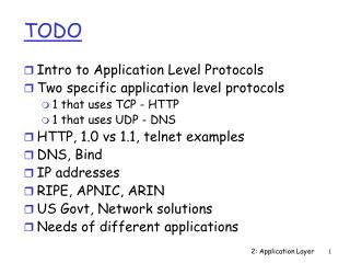
Agenda • IP functions • IP header format • IP routing • Fragmentation • IPng’s overview
Connectionless Delivery System • Most fundamental internet service consists of a packet delivery system • Service is defined as • Unreliable • Best-effort • Connectionless
Purpose Of Internet Protocol • Protocol that defines the unreliable, connectionless delivery mechanism is called Internet Protocol and usually called IP • IP has 3 important definitions • Basic unit of data transfer used throughout a TCP/IP internet • IP software perform the routing function • Including a set of rule that embody the idea of unreliable packet delivery
IP layer • defines a single virtual network on top of different kinds of hardware platform using IP address • functions of IP • route packet • fragmentation • handle type of services • send and receive error and control message using ICMP
IP attributes • handle data unit called IP datagrams • connectionless protocol - doesn’t promise reliable delivery • best effort delivery • packets may be lost, out out sequence, or duplicated due to various reasons
IP encapsulation • with Ethernet frame IP datagrams Ethernet hdr IP header data
0:0:c:6:13:4a 0:0:e8:15:cc:c 0x800 158.108.33.4 158.108.2.71 MAC dest MAC src type IP source IP dest 0:0:33:10:a:c 0:0:c:6:12:40 0x800 158.108.33.4 158.108.2.71 MAC dest MAC src type IP source IP dest packet from router packet to router IP reframing • IP will reframe the packet when A send data to B IP 158.108.33.1 MAC 0:0:c:6:13:4a IP 158.108.2.1 MAC 0:0:c:6:12:40 IP 158.108.33.4 MAC 0:0:e8:15:cc:c IP 158.108.2.71 MAC 0:0:33:10:a:c B A Change MAC address, IP address be the same
IP datagrams 0 15 16 31 vers:4 hlen:4 TOS:8 total length:16 identification:16 flags:3 frag offset:13 time to live:8 protocol:8 header checksum :16 source address :32 destination address :32 options and padding :32 data : 20 bytes
IP header details (1) • vers - version = 4 • hlen - header length in 32-bit words, • with no options, hlen = 5 = 20 bytes • TOS - type of service, desired quality of services 0 1 2 3 4 5 6 7 Prec. D T R 0 0 bits if 0 if 1 0-2 Precedence 3 Normal delay Low delay 4 Normal throughput High throughput 5 Normal Reliability High reliability 6-7 Reserved
IP header details (2) • Total length - length of datagrams (incl. header), max datagrams is 64K • identification, flags, fragmentation - use to segmentation and reassembly packet • TTL - Time to live, defining max number of routers through which the datagrams may pass (hop count) ttl-- decrease each router it passes a router normally set to 30 if ttl == 0 discard and send ICMP TTL exceeded to source IP (prevent looping)
IP header details (3) • Protocol - higher-level protocol that provides data 1 = datagrams carries an ICMP messages 6 = datagrams carries an TCP segments 17 = datagrams carries an UDP datagrams • header checksum - 16 bit one’s compliment, note that there is no data checksum • source address - 32 bit IP source address • destination address - 32 bit IP destination address • option and padding - additional info to control functions such as routing and security
Routing • routing is a process of choosing a path over which to send datagrams • IP routes packet by looking at the IP network number • routing components determine what path are available selecting the best path for a particular purpose using those paths to reach other networks • devices which perform routing are routers (historically call IP gateways)
Routing Table • Every router contains a routing table of the network numbers • The table records • which connection can be used to reach a particular network • plus some indication of the performance or cost of using connection
Routing Table form • Routing Table form • <network, gateways, others> % netstat -rn Destination Gateway Genmask Flags MSS Window irtt Iface 158.108.32.0 0.0.0.0 255.255.255.192 U 1500 0 0 eth0 127.0.0.0 0.0.0.0 255.0.0.0 U 3584 0 0 lo 0.0.0.0 158.108.32.1 0.0.0.0 UG 1500 0 0 e
How to create routing table • IP does not create routing table by itself • Normal 3 ways to create routing table • static route - by hand % route add 158.108.20.0 158.108.33.1 • dynamic routes - via routing protocol • via ICMP redirect
Routing Protocol • Routing protocol manages and updates routing table on each network node • often implemented in UNIX using one of the two daemons: • routed : basic routing daemon for interior routing, normally with RIP • gated : sophisticated daemon for interior and exterior routing, with additional protocol such as OSPF, BGP
MTU revisited for fragmentation • The upper limit number of data byte in data link frame is call MTU (Maximum Transfer Unit) • Typical MTU (bytes) FDDI : 4325 Ethernet : 1500 802.3 : 1492 Point-to-Point : 296 • If #bytes of datagrams to send>link layer’s MTU, IP breaks the datagrams up into smaller pieces (fragmentation)
Fragmentation • fragmentation = processed used by IP to reduced size of datagram that are too big for link connection MTU e.g. fragment 2000 bytes to Ethernet (MTU=1500) • fragments should be reassembled at the final destination (expensive process) • How ? • each fragment has its own header • each fragment carries the same 16 bit identification number • Each fragment must be aligned with an eight-octet boundary
Fragmentation flag • Identification number 16 bits integer value used to identify all fragments This id is not a sequence number! • flags - 3 bits control fragmentation 0= may fragment 1= don’t fragment 0= last fragment 1= more fragments reserve, must be 0 R DF MF • fragment offset - indicate the distance of fragment data from the start of the original datagram, measure in 8 octets unit
Fragmentation sample other header ident flags offset data ……. 232 0 0 0..2000 original 20 bytes 20 bytes Ethernet with MTU of 1500 ... 111 1 0 0..1479 ... 111 0 185 1480..2000 identification number more fragment last fragment post 185*8=1480 post 0
Problem in fragmentation • The end node has no way of knowing how many fragments there be. It has to manage enough buffer space to handle reassembly process. • If any fragments lost, all datagram must be discarded • End node starts a timer when received the first fragment, if any fragments fails to arrive (usually 30 secs), all datagrams must be discarded • Since the IP service is connection's. No attempt is made by IP to recover these situations, though ICMP error message may be generated
Path MTU • Path MTU : the smallest MTU of data link between two distance hosts • Need not to be constant because routing mechanism • Avoid fragmentation by discover PATH MTU (RFC1191) • Use ICMP to determine PATH MTU
Avoiding fragmentation • For datagrams within the same physical network, the MTU is known. TCP/UDP then use the MTU to limit the message size pass to IP; messages will never be fragmented. • For datagrams passed to diff net, not easy to know the MTU! • standard recommends that all networks supporting TCP/IP have an MTU of at least 576 bytes512 bytes data+20 bytes TCP hdr + 20 bytes IP hdr with optionsTO GUARANTEED THAT A PACKET OF 576 BYTES OR LESS IS NEVER FRAGMENTED
IPng • Problem of current IP address : limitation of 32 bit address space • 1990 : IETF defined a new version of IP, generally called IP Next Generation or IPng • Spring 1992 : IAB issues IPv7, proposed the OSI CLNP (connectionless Network Protocol) as the basis of IPv7. Finally rejected by IETF and working groups
IPV6 • End 1992: 7 proposals for IPng CNAT, IP Encaps, Nimrod, Simple CLNP, P Internet Protocol, SIP, and TP/IX • resolution to 3 possibilities : SIP+ TP/IX => TUBA (TCP and UDP with bigger Address: RFC 1347) TP/IX => CATNIP (Common Architecture for the Next Generation Internet Protocol :RFC1707) SIP+IP encaps+PIP=> SIPP (Simple Internet Protocol Plus: RFC1710) • Mid 1994 : SIPP was chosen, known as IP version 6 (IPv6)
IPv6 Header 0 15 16 31 vers:4 flow lable:28 payload length:16 next hdr:8 hop limit:8 destination address :128 source address :128 40 bytes 40 bytes fixed length header, no checksum, options are replace by additional extension header
IPV6 address representation • 16 bits eight hexadecimal value e.g. 4210:30:127F:9111:7801:DA0A:3232:44 5510:0:0:0:0:0:0:44 or 5510::44 • Address with mixed environment of v4 and v6 x:x:x:x:x:x:d.d.d.d e.g. 0:0:0:0:0:0.158.108.2.71
IPV6 key advantages • 16 bytes fix length IP address support ~1000 million networks • IPv4 compatibility • self-configuration of workstations • support mobile workstations • improved security features