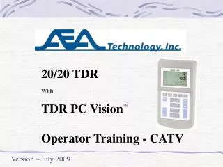
20/20 TDR With TDR PC Vision Operator Training - CATV
20/20 TDR With TDR PC Vision Operator Training - CATV. TM. Version – July 2009. Training Subjects. Section Title Slide # Introduction, Power and the CD-ROM 2 - 6 Powering ON & Menus 7 - 15 How TDRs work 16 - 21 Step TDR reflections 22 - 27

20/20 TDR With TDR PC Vision Operator Training - CATV
E N D
Presentation Transcript
20/20 TDR With TDR PC Vision Operator Training - CATV TM Version – July 2009
Training Subjects Section TitleSlide # Introduction, Power and the CD-ROM 2 - 6 Powering ON & Menus 7 - 15 How TDRs work 16 - 21 Step TDR reflections 22 - 27 20/20 TDR Measurement Screen & Keypad 28 - 31 Premise application on Twisted Pair Cable 32 - 39 Coax and OSP Applications 40 - 43 Advanced Features (optional) 44 - 49 Saving Traces and TDR PC Vision (optional) 50 - 64 Cleaning, Maintenance, Warranty & Tech Support 65 - 66 Q & A and Acknowledgements 67 1
Made in theUSA What’s in the Box? 2
F connector or Network units with an RJ-45 and F connectors Quarter VGA backlit LCD Ruggedized weather resistant keypad with high tactile feel for use with gloves Solid ABS plastic case 3
CAUTION NO mixing cells Same Type & mAhr Battery Installation F2 BATTERY MENU Select Alkaline or NiMH/NiCd and enter rated mAhrs 4
AC or DC Power and Recharging (Included with Rechargeable TDRs) 12.5 VDC @ 500 mA Vehicle running is preferred DC power permits operation OR recharging, but not both 100-240 VAC 50/60 Hz AC power permits operation AND Recharging 5
CD Directory TDR PC VisionTM - - - - - - - - - MS Windows software loadable to any number of PCs TDR Application Notes - - - - - 20+ Details Notes on TDR uses Operation Manual Quick Start Guide Electronic Copies Training PPT - - - - - - - - - - - - General/Broadcast Training CATV Technician Telephone Technician CD-ROM www.aeatechnology.com 6
Powering ON Pressing ON starts the unit, performs a self-check and restores the last used settings Powering ON with Soft Reset Press ON and then quickly pressing ENTER 4 – 5 times performs a soft reset and restores factory default settings 7
HIGH VOLTAGE DETECTED Try pressing ENTER 1 or 2 times to see if the detection clears If it will not clear, there is more than 100 VDC or 0.5VAC on the line being tested. Use precautions to remove the TDR and remove or reduce the voltage prior to retesting. The 20/20 TDR is protected to 300VAC and 300VDC 8
F1 First press F2 UNIT SETTINGS: BACKLIGHT, CONTRAST AUDIO, BATT SAVER, BAUD, SELF TEST F3 DATA DISPLAY: SCALES, GRIDS, UNITS OHMS/SWR/DB, SCREEN FROMAT F4 UTILITIES: FAULT/INTERMITTENT FIND FILTERS, MEM SAVE/RECALL, CH SEL F5 CABLES: VIEW, CATALOGS, SELECT, EDIT CABLE SAMPLER, TEST LEAD CALIBRATION RJ45 TP- TKN CH TEL 568A 568B USOC 10BT PMD RING A R/B PR1 PR1 PR1 RX B G/B PR2 PR3 PR2 RX TX C PR3 PR2 PR4 TX RX D PR4 PR4 PR3 TX AB RG 12 13 12 TR AC 13 12 14 AD 14 14 13 BC 23 23 24 TR BD 24 34 23 CD 34 24 34 TR If using a Network TDR Second press F-Keys Menu, Channel Guide & ESC Escape Key When in Menus F2 – F5 Press to escape back to the Measurement Screen Backspace Key When in an numeric entry screen, F1 erases the last character entered and jumps back one space 9
Any arrow key will move the selection left/right or Increase/decrease numbers for the menu item marked Function Key Item & Selection Navigation BACKLIGHT TIMER :OFF BRIGHTNESS :8 CONTRAST :8 AUDIO VOLUME :0 ……….. 10 20 50 10
F2 BATTERY MENU : Internal re-chargeable TDRs have a sub-menu Key – Unit Settings BACKLIGHT TIMER :OFF {10, 20, 50 sweeps & continuous} BRIGHTNESS :8 {range 0 to 10} CONTRAST :8 {range 1 to 15} up for colder temps AUDIO VOLUME :0 {range 0 to 3} AUDIO MODE :OFF, KEY BEEP, CONTINUOUS BAUD RATE :57600 {range 4800, 9600, 19200, 28800} BATTERY SAVER :OFF, ON SELF TEST :OFF {test list & keypad checker} 11
F2 BATTERY MENU : BATTERY SAVER: ON, OFF BATTERY TYPE : NICD NIMH, ALKALINE, NONE BATT CAPACITY : 2000 MAHR {400 – 5300 mAhr} EST. RUN TIME : > 7.0 HRS {Max to 0.0 hrs} BATTERY STATUS : 10.7V -220MA BATTERY TEMP : TEMPERATURE OK {HOT, COLD} CHARGER STATUS: IDLE {BATT CHK, PRE CHRG, CHARGING, TRICKLE} Key – Unit Settings 12
F3 Rechargeable TDRs are Z OHMS only Key – Data Display Options V SCALE : 100 {range 20, 50, 100, 200, 500, 1000} H SPAN : 20 {range 20 to 10,000} PLOT START : 0 {range 0 to 2,500} UNITS : FEET, METERS GRID LINES : 0 {range 0 to 4} BIG NUMBERS : OFF, ON PLOT TYPE : Z OMHS, SWR, RTN AMPL DB 13
F4 Rechargeable TDRs have only STEP mode display Key – Special Functions MEMORY ACTION : ◄► TO SAVE/RECALL NOISE FILTER : 0 {range 0 to 4} AVERAGING FLTR : 0 {range 0 to 7} VIDEO FILTER : 0 {range 0 to 4} INTRMTENT GRAB : OFF, ON FAULT FINDER : OFF, ON STEP OR PULSE : STEP, PULSE INPUT CHANNEL : INPUT COAX, RJ45 CHs A, B, C, D, AB, AC, AD, BC, BD, CD 14
F5 Key - Cable Operations AEA CABLE LIST {Cables listed by MFG, P/N, Type & Zo} VIEW USER LIST {56 User Defined Cables} EDIT USER LIST {Define or Alter a Cables Details & Store} TEST LEAD CAL {Removes the test lead from the plot} SAMPLE A CABLE {Find a Cable’s Velocity Factor} CURRENT CABLE: COMSCOPE .625 P3------------Z 75 VF 87.0 15
Time How Does a TDR Work? The same as RADAR 16
Time 2 X Velocity = Distance 20 n Sec 2 X .66c (648,172,800ft/sec) = 64.8 feet VoP or NVP VF or VP Beware of VF Uncertainty Cable Velocity and Distance Velocity is designed in a cable at the time of its manufacture Velocity is expressed as a fraction of the speed of light Example: .66c 17
Impedance “Z” Z = 100 Ohms Z = 75 Ohms 18
Z = ∞Ω Zo=75 or 100 Open Zo=75 or 100 Z = 0 Short Cable Impedance (Z) and Reflections Impedance is a factor of both the conductor and the dielectric of the insulation between the conductor & shield or twisted pairs Any deviation from the manufactured Z will cause reflections 19
Pulse TDR Pulse TDR Longer and Longer Dead Zones 20
Step TDR Step TDR = No Dead Zones – Any Range 21
Mixed Impedances Bridged Tap Pinched Coax Water Split Pair That Resplits Poor Quality Coax Poor Splice 1 9 1 2 10 3 Example Step TDR Reflections What a “Pulse TDR” Cannot See 22
TDR Trace Cable Type Velocity Factor Vertical Scale or V-Scale (Z) VF 85.0 COMMSCOPE Drop F6 100 Cursor 1 87.5 75 62.5 50 0 20 40 CRSR1 19ft 10in 78.4 to 78.6Ω Horizontal Span or H-Span (Feet or Meters) Cursor Information 20/20 Step TDR Display 23
Example 20/20 “Step” TDR Traces Open Cable or Pair Shorted Cable or Pair Opens and shorts send the trace to maximum or zero Ohms respectively. Unlike a pulse TDR, there is no trace after these events 24
Example 20/20 “Step” TDR Traces Bad Connector on RG-59 Mixed Z, 75 then 50 Ohm Both events will cause unwanted signal reflections. The 50 Ohm cable will add extra signal attenuation 25
Example 20/20 “Step” TDR Traces Good Splice Poor Splice These splices are in 100 Ohm twisted pair cable, but will appear similar in coaxial cable 26
Example 20/20 “Step” TDR Traces Wet Cable Split and Resplit Splits and resplits are common in home wiring where the owner didn’t understand the importance of pairing Wet cable always show an erratic downward excursion on the trace. 27
GENERIC 24AWG VF 66.7 125 112 100 87 75 0 20 40 CRSR1 19ft 10in 100.4 to 100.6 GENERIC 24AWG VF 66.7 125 112 100 87 75 0 40 80 CRSR1 39ft 8in 100.5 to 100.7 GENERIC 24AWG VF 66.7 125 112 100 87 75 0 80 160 CRSR1 79ft 6in 100.4 to 100.6 Zoom Key 28
GENERIC 24AWG VF 66.7 125 112 100 87 75 0 20 40 CRSR1 19ft 10in 100.4 to 100.6 GENERIC 24AWG VF 66.7 125 112 100 87 75 40 60 20 CRSR1 39ft 8in 100.5 to 100.7 GENERIC 24AWG VF 66.7 125 112 100 87 75 80 40 60 CRSR1 59ft 6in 85.1 to 86.4 Step Key 29
GENERIC 24AWG VF 66.7 200 150 100 50 0 0 20 40 CRSR1 19ft 10in 100.4 to 100.6 GENERIC 24AWG VF 66.7 500 375 250 125 0 0 20 40 CRSR1 19ft 10in 100.4 to 100.6 Scale Key 30
Exam/Plot freezes or Un-freezes the active plot Cursor Keys activate, move & de-activate either cursor Enter saves menu changes & returns to Measurement Display, Cursor Hide/Unhide key Power OFF Saves All Settings Remaining Keypad Keys 31
Transition from the Theoretical to the Practical How can a TDR help you get a clear TV picture, a quality phone call or a fast internet connection 32
Bedroom 1 Bedroom 1 Living Room Living Room Bedroom 2 Bedroom 2 RJ45 Wired USOC 1 – T4 White/Brown 2 – T3 White/Green 3 – T2 White/Orange 4 – R1 Blue 5 – T1 White/Blue 6 – R2 Orange 7 – R3 Green 8 – R4 Brown Bedroom 3 Bedroom 3 Kitchen Kitchen NID RJ12 Wired USOC RJ12 Wired USOC RJ11 Wired USOC Typical Telco Loop Wiring 1 – T3 White/Green 2 – T2 White/Orange 3 – R1 Blue 4 – T1 White/Blue 5 – R2 Orange 6 – R3 Green 1 – T3 not connected 2 – T2 Black 3 – R1 Red 4 – T1 Green 5 – R2 Yellow 6 – R3 not connected 1 – T2 Black 2 – R1 Red 3 – T1 Green 4 – R2 Yellow Telco USOC Wiring Scheme for Homes and Small Businesses 33
RJ45 Wired T-568A RJ45 Wired T-568B Kitchen 1 – T3 White/Green 2 – T3 Green 3 – T2 White/Orange 4 – R1 Blue 5 – T1 White/Blue 6 – R2 Orange 7 – R4 White/Brown 8 – R4 Brown 1 – T3 White/Orange 2 – T3 Orange 3 – T2 White/Green 4 – R1 Blue 5 – T1 White/Blue 6 – R2 Green 7 – R4 White/Brown 8 – R4 Brown Living Room Bedroom 1 Bedroom 2 Bedroom 3 NID Typical Star or Home Run Wiring TIA 568B for Business Wiring or TIA 570B for Residential Wiring 66 Block or 110 Block or Connection Box 34
AEA Technology Reduced All Wiring Schemes to Coax & 4 Channels • 99.9% of all phone lines will be on TDR’s Channel A • The 20/20 TDR menu simplifies looking at any single pair or the difference between any two pairs • The 20/20 TDR is impedance independent and can test both coax and twisted pair cables with the same TDR • The 20/20 TDR has a customized cable list for CATV techs that covers OSP coax, Premise coax and twisted pairs for Cat 2 through Cat 6 35
Bedroom 1 Bedroom 1 Living Room Living Room Bedroom 2 Bedroom 2 Bedroom 3 Bedroom 3 Kitchen Kitchen Shorting Plug GENERIC 24AWG VF 66.7 GENERIC 24AWG 200 VF 66.7 200 150 150 100 100 50 50 0 0 0 160 320 0 160 320 CRSR1 291ft 10in 101.4 to 101.6 CRSR1 291ft 10in 101.4 to 101.6 Three Step Check • Unplug all • phones • Connect the • TDR at NID • Locate end • jack using a • shorting plug NID Results Open and short at end jack indicates a good pair run. Test can be repeated for all pairs. 36
Shorting Plug Shorting Plug Shorting Plug Bedroom 1 Bedroom 1 Living Room Living Room Bedroom 2 Bedroom 2 Bedroom 3 Bedroom 3 Kitchen Kitchen NID GENERIC 24AWG GENERIC 24AWG VF 66.7 VF 66.7 200 200 150 150 100 100 50 50 0 0 0 160 320 0 160 320 CRSR1 155ft 3in 101.4 to 101.6 CRSR1 155ft 3in 101.4 to 101.6 Three Step Check • Unplug all • phones • Connect the • TDR at NID • Locate last • visible jack • using a shorting • plug Results Fault is a broken wire after the jack connection in Bedroom 1’s jack 37
Bedroom 1 Bedroom 1 Living Room Living Room Bedroom 2 Bedroom 2 Bedroom 3 Bedroom 3 Kitchen Kitchen NID GENERIC 24AWG VF 66.7 200 150 100 50 0 0 160 320 CRSR1 174ft 7in 101.5 to 101.8 Three Step Check • Unplug all • phones • Connect the • TDR at NID • Note short at • Bedroom 2 • with no shorting • plug. Results Look for bent pins or shorted wires inside the jack 38
Premise Advantage of a TDR? • Quickly locate the distance to a fault and see type of fault • Stop rewiring premise twisted pairs when a simple 5 minute fix will clear the trouble • 95% of all premise telco wiring problems are in the jacks 1. Customer pulled out jack and broke a wire 2. Customer rewired jack and disrupted service 3. Bent or broken pins 4. Cat marked territory and corroded jack pins 39
OSP Testing and Fault Locating • Range Maximums: velocity dependent – 6,600 ft @ .66c 8,800 ft @ .88c • Measure Cable’s Impedance (Z) & Resistance (Ω) via “Dribble Up” • Use Noise, Averaging or Video Filters to clear the trace • Locates Distance and Impedance effects for: Poor Splices Bad Connections Cable Kinks Cable Damage Water & wet taps Network Devices Impedance Mismatches Lossy Cable 40
20/20 “Step” TDR COMMSCOPE 0.540 VF 88.0 200 150 100 50 0 0 1280 2560 CRSR1 1157ft 0in 96.9 to 97.6 CRSR2 1096ft 0in 85.8 to 86.1 CRSR 61ft 0in 11.1 to 11.5 Poor Splice or Bad Connection Pulse TDR COMMSCOPE 0.540 VF 88.0 0 1280 2560 1096ft CRSR Step TDR’s Advantages 1. Series resistive fault with over 11 Ohms of loss in one spot. 2. Both cable sections exhibit normal resistive loss as evidenced by the “Dribble Up” 41
COMMSCOPE 0.540 VF 88.0 200 150 100 50 0 0 640 1280 CRSR1 599ft 7in 80.4 to 80.6 311 ft 599 ft 1374 ft Water in OSP Cabling • Water Rules • Reduces the resistance of • the dielectric or insulation - • Hence reduces cable’s Z. • Reduces velocity to an • unknown – Hence distances in • a water slug or after the slug are • NOT valid. 464 ft water 42
COMMSCOPE 0.540 VF 88.0 200 COMMSCOPE 0.540 VF 88.0 200 150 150 100 100 50 0 50 0 1280 2560 0 CRSR1 1423ft 10in 88.5 to 89.0 0 640 1280 CRSR1 642ft 0in 86.3 to 86.7 CRSR2 610ft 7in 80.5 to 80.8 Network Device CRSR 31ft 5in 5.8 to 5.9 Impedance Mismatch & Lossy Cable Section Network Devices and Impedance Mismatches 43
20/20 TDR’s Advanced Features Differential Mode ------------ Compares one twisted pair to another twisted pair and shows any differences Intermittent Grabber --------- Permits looking for a short or open and moving the cable or connectors to find an intermittent fault Fault Finder ------------------- Set upper and lower impedance limits, the TDR will jump the cursor to the first point exceeding the limit. SWR Mode ------------------ Provides calculated Standing Wave Ratio of the cable along it’s length Return Amplitude ---------- Provides calculated Return Amplitude in dB for mismatch events 44
3. Press and select INPUT CHANNEL 4.Press any key as required to select RJ45 AΔB for telco leads difference or any other RJ45 xΔx as desired, see QRG table Using Differential Mode 1.Measure a single pair in a cable and and note the events • Connect the telco test leads’ Green/Black pair or use an RJ45 • plug input for access to another of the four pairs 5. Press ENTER 45
2. Press select INTRMTENT GRAB and press any key to turn ON Intermittent Grabber Mode 1. Connect the cable with the suspect intermittent fault and full trace 3. Hand-over-hand move along the cable flexing and moving sections and connection points to induce the fault NOTE: If the entire trace goes erratic, change the termination & try again. The fault and the cable’s termination must match for a correct display. 46
150 100 75 50 0 AUTO FAULT LOCATION UP/DOWN MOVES CURSOR, F1=ESCAPE LEFT/RIGHT CHANGES SETTING ENTER RESUMES NORMAL OPERATION ->AUTO FAULT : OFF MINIMUM OHMS : 64 MAXIMUM OHMS : 86 86 64 2. Press and select FAULT FINDER then press 3. Press to select AUTO FAULT: ON 4. Press to select MINIMUM OHMS, then MAXIMUM OHMS and enter the limits for each when prompted Fault Finder Mode 1. Connect the cable and set the full trace on the display 5. Press ENTER to return to Measurement Screen and CURSOR 1 will jump to the first minimum or maximum detected 47
1. Press then select PLOT TYPE and press 2. Press again to change from Z OHMS to SWR SWR Mode 3. Press ENTER Note the changed vertical scale and cursor readouts for SWR 48
1. Press then select PLOT TYPE and press 2. Press again to change from SWR to RTN AMPL DB Return Amplitude Mode 3. Press ENTER Note the changed vertical scale and cursor readouts are now in dB 49