Download
1 / 112
1.14k likes | 1.37k Vues
Miranda Integrated Master Control Provided by: Miranda Technologies. Classroom Rules…. Training Materials…. Course Syllabus Presentations used in the class Training Manual (in PDF) Exercises and Home work handouts Training Evaluation Final Exams. Cellular phones not allowed.

E N D
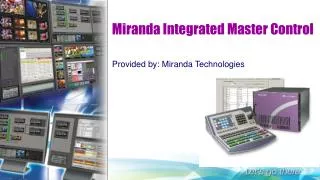
Miranda Integrated Master Control Provided by: Miranda Technologies
Classroom Rules… Training Materials… • Course Syllabus • Presentations used in the class • Training Manual (in PDF) • Exercises and Home work handouts • Training Evaluation • Final Exams • Cellular phones not allowed. • No access to emails or Internet in Classroom. • Students required to remain in the class for duration of the day. • Regularly scheduled breaks.
Introduction to the IMC System • IMC System components may include Imagestore 750, ImagestoreModulars and Control Panels. • Communicate via Ethernet LAN. • Control Panel will issue a commands to attached channel (IS-750 and Imagestore Modular • Channel responds with status and executes command. • When successful channel notifies panel and updates its displays and indicators accordingly.
Introduction to the iMC System • iMC works in conjunction with NV9000 router control system, allowing channel access to entire router input space and providing the ability to select any router source. • Many control panels can control more than one channel at a time – although usually channels managed one at a time. • When Channel changed, control panel update takes about a second. • Panel attaches to newly selected channel and provides the new channel’s specific source layout, transition rates and layer presets. • Automation can also control channels.
Control Panels for the iMC System Presently 3 hardware and 1 software (GUI) panels available: • iMC-Panel-GUI: Software control panel. • Runs on PC and provides graphical user interface. • It is software emulation of iMC-Panel-200. • Designed to work with or without touch screen. • iMC-Panel-100: 3RU rack-mounted panel with separate rack- mountable display. • Sleek design with just over 2 inch depth.
Control Panels for the iMC System • iMC-Panel-200: Compact hardware CP with large LCD touch screen, many function buttons and joystick. • Mounts on desktop or work surface. • All buttons have LCD legends and color-coding. • iMC-Panel-300: Full size CP with large LCD touch screen and many function buttons as well as joystick. • Mounts on desktop or work surface. • All but two buttons have LCD legends and color-coding.
Other Miranda products Intuition XG: • Single- or dual-channel HD\SD graphics processor. • Stores XG media clips, transmits clips (fill \ key) when directed
Imagestore 750 Overview • Channel branding processor. • Operates as stand-alone device with or without automation or as part of Miranda’s IMC System (750/NV5100MC master control system). • Combined with NV9000 router control system it provides video/audio sources and one or more MC panels (such as iMC-300) that provide commands. • IS-750 provides switching instructions to NV9000 when it receives commands from MC panel. • IS-750 essentially A/B transition processor that inserts video effects (DVEs and DSKs) and voice-overs into its output. • Occur many configuration options (covered in IS-750 training).
Imagestore 750 block diagram Input and outputs include: • 4 x SDI IN, A-D. • Accept HD or SD. • 2 x External keyer pairs (fill and key). • IN C/D can be used for third keyer pair. • 16 x GPIO (IN or Out, LTC and Dolby metadata). • 16 X AES IN and 16 AES OUT. • 4 x SDI outputs (PGM / PWV / Clean feed / monitor). • Also 4 COM ports and 2 Ethernet ports.
Imagestore 750 video processing: • Select an input (A,B,C,D, Fill1, Key1, Fill 2, Key 2) individually as SDI or as one of 5 test signals. • Each SDI input can be subject to a rectangular clipping mask. • Inputs C / D can be used as pair (Fill 3, Key3). • Any fill/key input can receive clips from Intuition XG processor. • Similarly DVEs can connect to any input. • DVEs can also accept output of A/B mixer. • DVE output can be inserted in one of three places of the processing path: • Before DSK1, before DSK2 or before DSK3.
Imagestore 750 video processing: • IS-750 also has storage for supporting internal keyers (logos, etc). • Preview output can present video from one of several tap points. • Similarly CLN and MON outputs can present video from several different tap points.
Control Panel features Configurable function buttons: • Requirements of buttons vary according to needs of facility and operator. • When controlling IS-750, iMC-Panel-300 has 5 sets of customer-definable buttons. Channel selection, including ‘no channel’ mode and ‘ganged channels’: • Typically panel has assigned channel on boot-up. • May be configured so default channel part of channel gang. • This referred to as ‘automatic gang mode’. • When this channel selected, all channels in gang are selected.
Control Panel features Salvos: • iMC-Panel-300 can trigger NV9000 system salvo each time channel change occurs. • Example: salvo can change entire audio/video monitor configuration instantly. • Independent downstream keyers (DSKs): • When controlling IS-750, panel can control 4 independent (linear) DSKs, each with separate key and fill inputs. • Key parameters (i.e. clip, gain, transparency) configured independently on each IS-750. • DSKs handle internal keys (stills / animations) plus up to 3 external keys.
Control Panel features DVEs: • DVE (digital video effect) is sequence of operations that can dynamically scale and position a video image on the screen, overlaying the main source. • DVE can perform other effects too. • Created with DVE Editor. Stored in IS-750. • XG Layers: • XG layer (or clip) is one of up to 8 outputs of Intuition XG processor. • When controlling IS-750, panel can control up to 8 XG layers. • XG layers are processed by one of DSKs. • Usually there is default DSK assigned to XG layers.
Control Panel features Fade to black: • Provides fade-to-black and fade-to-silence function. • General-purpose I/O (GPIO). • CP have two optically isolated inputs that can sense external events and two relay outputs that trigger external events. • Audio metering and monitoring: • When iMC-Panel-300 is controlling IS-750, Audio Monitoring section has customer-configurable buttons. • Knobs control overall audio gain for IS-750 CLN and MON outputs.
Control Panel features Audio channel control: • IS-750 processes 16 audio channels. • IS-750 has 5 audio sections: • Program input audio • Program output audio • Preset input audio • Voice over 1 audio • Voice over 2 audio Panel lock: • Use to prevent accidental changes to panel settings. • Source groups: • Up to 24 main source buttons. • IS-750 allows definition of multiple source groups. • Each group can be mapped to main source buttons of iMC-Panel-300. • Sources in group selected from sources defined in NV9000 System. • Thus all NV9000 sources are potentially accessible.
iMC-Panel-300 summary • Configurable master control panel. • 28.25” wide x 6.96” high x 20.14” deep. • Sits on console or desk top.
iMC-Panel-300 Side and Rear view
iMC-Panel-300 summary • Top left -- 16 customer-definable function buttons. • Top right -- Group of audio monitor and meter controls. • Knobs -- Control IS-750 CLN audio and MON audio outputs. • 2 (red) audio level knobs. Red as they control on-air signals. • Top center -- 3-axis joystick. • Lower front surface are 4 rows of 24 buttons: • Preset – Program - Preview/User – Aux/User • Preset / program rows contain up to 24 main sources and 8 video effects and up to 2 voice-overs. • Video effects and voice-over buttons can be configured in any order, but effects executed in configurable order in the IS-750.
iMC-Panel-300 summary • Preset and Program buttons identical. • Represent same sources, video effects and voice-overs. • Paired (and identical) and support content and transitions going on air. • Preview/User buttons when panel controlling IS-750 are set of 24-customer-deablable buttons among which are menu buttons. (Menu buttons select menus on touch screen. • Aux/User buttons include same main sources as program and preset. • Provides up to 6 customer-definable buttons (at right) instead of video effects and voice-over. • Aux buttons provide means to direct selected router source to auxiliary device such as a monitor.
iMC-Panel-300 front panel • Front of panel are two groups of function buttons. • Group of 12 are Transition control buttons by convention. • Group of 3 buttons are System Control buttons by convention. • All are configurable. • Right front is (orange) transition button which is not configurable.
iMC-Panel-300 rear connectors • Rear of panel are two power connectors, GPI/Alarms connector, Ethernet port, USB port, an aux port and SD/HD input (BNC). • USB port reserved for future development. • SD/HD input connector (BNC) is panel audio metering input. Not used with IS-750.
Sections of iMC-Panel-300 • Program buttons • Preset buttons • Preview/user buttons • Aux/user buttons • Configurable buttons • LCD touch screen • Joystick • Audio monitor/meter section • Touch screen knobs • Audio level knobs • Transition control buttons • System control buttons • Transition button
Sections of iMC-Panel-300 • Program buttons: • 24 program buttons include main source and layer buttons. • Layer buttons – configure as video effects or voice-overs. • Number of main sources, video effects and voice-overs varies according to panel configuration. • Whatever main source, video effects and voice–overs selected on program buttons form program output of IS-750 that is currently controlled by panel. • Note: Preset/program buses behave differently under different transition options.
Sections of iMC-Panel-300 • Preset buttons: • Allow setup of state of program output that will exist after next transition. • Also include main source buttons and layer buttons. • Function assigned to program also assigned to preset button directly beneath it. • Whatever main source, video effects and voice-overs selected on preset bus form, preview output is of IS-750 currently being controlled by panel. • Note: Preset/program buses behave differently under different transition options.
Sections of iMC-Panel-300 • Preview/user buttons: • Customer-definable buttons when panel controlling IS-750. • Aux/user buttons: • When panel controlling IS-750, row contains AUX buttons and up to 6 customer-definable buttons. • AUX buttons are main source buttons. Main sources are same sources as on preset and program button rows. • Allows main source to be directed to aux device, such as a monitor. • IS-750 has aux bus follow ‘aux bus follow’ option. • Depending on how they’re set, aux buttons may follow program or preset bus or remain independent.
Sections of iMC-Panel-300 • Configurable buttons: • 16 buttons with LCD legends. • Each programmable to perform functions such as channel selection, menu selection or source group selection. • Some buttons can function as status indicators. • Buttons in other sections of panel also configurable. • LCD touch screen: • Color LCD touch screen allows for parameters to be adjusted and control system functions. • 8 rotary knobs are associated to touch screen for adjustment of parameters.
Sections of iMC-Panel-300 • Joystick: • Adjust certain parameters such as change size or position of DSK’s. • Audio monitor/meter section: • Two rotary knobs in ‛Audio Monitoring’ section labeled ‛Gain’. • These associated with rows: • Mon A / CLN • Mon B / MON • For IS-750 panel : • CLN gain knob controls audio level of IS-750 CLN output. • MON gain knob controls audio level of IS-750 MON output. • 12 buttons customer-configurable buttons. Others have no functions.
Sections of iMC-Panel-300 • Touch screen knobs: • 8 knobs under touch screen allow operator to adjust menu parameters. • Audio level knobs: • Duck Level • When controlling an IS-750, knob controls level at which main audio is dimmed when voice-over is mixed with PGM output. • Gain / Voice-Over preset • When controlling an IS-750, knob controls over level when voice-over is mixed with PGM output. • Knobs support only program audio.
Sections of iMC-Panel-300 • Transition control buttons: • Transition buttons. User configurable. • System control buttons: • Convention, system control buttons. User configurable. • Displays transition type (as a graphic) and transition rate (in text). • Transition button: • Cut transition involve no rate so no rate text exists for this button. • Pressing transition button initiates transition in IS-750 according to panel setup.
iMC-Panel-300 Touch screen • Presents number of different menus. • Adjust operating parameters. • Menu buttons allow for selection to appear on touch screen. • Menu buttons toggle. • Press once to display menu; again returns to Main menu. • Some menus allow function parameters such as DSK Rates, CGT and Keying menu to be managed. • Line at top of touch screen for status and error messages and a second for informative messages.
iMC-Panel-300 Configurable buttons Definable button functions: • LCD – 3 rows of 8 characters. • Color definable. • Classes available for IS-750: • Channel selection • Transition type • Transition rate • Salvo • Automation assist • System Control • Menu
iMC-Panel-300 Audio levels Program audio: • Affects only program audio. • Two sections: • Duck-Level • Gain / Voice-Over Preset Duck level Knob • For IS-750 controls level that main audio is dimmed when voice-over mixed with program output. • Adjusts in increments of 0.5 Db. Gain / Voice-Over Preset Knob • When panel controls IS-750, controls over level when voice-over mixed with program output. • Adjusts in increments of 0.5 Db.
iMC-Panel-300 Joystick • 3-axes: up, down, left, right. • Considered X- and Y-axes. • Change certain parameters. i.e. size or position of DSK’s. • Use to scroll through channels, video effects and other displays. • Also possible to select crosspoint in audio channel swap matrix. Left button function varies. Example could use to make audio crosspoint connection. Right button not used. Knurled “Z-axis” not used for IS-750
iMC-Panel-300 Monitor and Meter control • When controlling IS-750 buttons user configurable. • Often used for non-audio functionality. • Dim buttons are disabled. • CLN and MON apply to IS-750. • Knobs adjust audio level in increments of 0.05 dB, from -99.5 dB to +28.0 dB. • Monitoring knobs do NOT affect on-air levels.
iMC-Panel-300 Preset and Program buttons Program and preset buses divided into two parts: • Main source buttons • Typically green. High-tally when selected, low-tally when not. • If problem with main source it is high-tally amber when unselected and red when selected. Unused main sources are dark.
iMC-Panel-300 Preset and Program buttons Program and preset buses divided into two parts: • Layer buttons • Rightmost buttons can be configured as video effects or voice-overs.
iMC-Panel-300 Preset and Program buttons • Main source buttons and layer buttons together form two buses: • Program: Selections on Program bus compose program output of currently selected IS-750. • Preset: Selections on Preset bus preview content of program bus as it will appear after next transition.
iMC-Panel-300 Aux/User buttons • Aux/User buttons are located above or behind preview bus. • Divided into two parts: • Main source buttons: • Usually green, high-tally when selected. Low-tally when not. • Amber high-tally problem on source but it’s not selected. • Red problem on source and its currently selected.
iMC-Panel-300 Aux/User buttons • Aux/User buttons are located above or behind preview bus. • Divided into two parts: • Customer-definable buttons: • Rightmost buttons, if not committed to main sources are customer definable. • Up to 6 buttons in Aux/User row can be configurable.
iMC-Panel-300 buttons details • Main Source button characteristics: • Up to 8-character display. Following color scheme: • Touch screen displays source status. If OK no message text. • Following are possible fault conditions: • Note: priority of message is as shown.
iMC-Panel-300 Video Effects • Selected video effects overlay selected main video source. • Video effects cumulative and apply in order defined by IS-750. • DSK’s are applied: DSK1, DSK2, DSK3, DSK4. DSK4 is highest layer. • Downstream effects modify upstream effects and main source. • Upstream effects do not modify downstream effects.
iMC-Panel-300 Downstream Keyers • 4 keyer buttons are independent toggles. • Downstream keyer (DSK) active when its button is selected (high-tally) and inactive when its button is low-tally. • Note: DSK cannot be used when it is non-sync or LOS. • External key usually pair of video sources – key/fill. Key forms mask for Fill. • External keys can be provided by Intuition XG. • Internal key is stored still frame or animation. • Key source overlays upstream source (and upstream effects) with specified clip, gain, and transparency parameters that control key values. • Any DSK can be associated to any key source, including Intuition XG clips.
iMC-Panel-300 DVE • DVE buttons: • Independent toggles. • Active when associated is button high-tally / inactive when its low-tally. • Pre-configured with DVE stored in IS-750 • Button functions available to enable/disable DVEs on program and preset button rows.
iMC-Panel-300 Voice-overs • 2 voice-over button pairs on Program and Preset buses not mutually exclusive. • When over selected on Program row, its audio contributes to program audio. • When over selected on Preset row, becomes armed and plays at next transition. • An over function mixes selected audio source to air, but does not trigger audio playback of source device. • Voice-Over Button Characteristics: