Download
1 / 49
510 likes | 744 Vues
Antennas and Propagation. Chapter 5. Introduction. An antenna is an electrical conductor or system of conductors Transmission - radiates electromagnetic energy into space (involves both E and H fields) Reception - collects electromagnetic energy from space

E N D
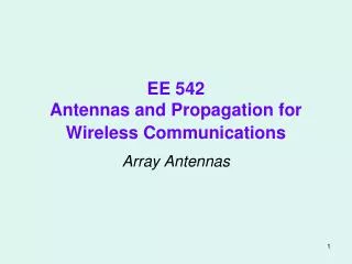
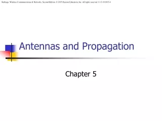
Antennas and Propagation Chapter 5
Introduction • An antenna is an electrical conductor or system of conductors • Transmission - radiates electromagnetic energy into space (involves both E and H fields) • Reception - collects electromagnetic energy from space • In two-way communication, the same antenna can be used for transmission and reception (simplex or with duplexers to isolate the different transmit and receive frequencies) • Reference Data for Radio Engineers and similar handbooks provide good reference sources for antennas and propagation topics
Radiation Patterns • Radiation pattern • A graphical representation of the radiation properties of an antenna (far-field) • Idealized (perfect ground), impacts by the surrounding environment normally neglected • Depicted as two-dimensional cross section (elevation & azimuth) • Beam width (or half-power beam width) • Measure of directivity of antenna • Reception pattern • Receiving antenna’s equivalent to radiation pattern • Antenna modeling software very common tool (computer based and very accurate, e.g., NEC, MININEC)
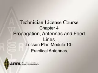
Types of Antennas • Isotropic antenna (idealized, free space environment) • Radiates power equally in all directions • Dipole antennas • Half-wave dipole antenna (or Hertz antenna) • Quarter-wave vertical antenna (or Marconi antenna, normally vertically polarized) • Parabolic Reflective Antenna • Focus
Antenna Gain • Antenna Gain (Directivity) • Power output, in a particular direction, compared to that produced in any direction by a perfect omnidirectional antenna [usual reference is an isotropic antenna (dBi) but sometimes a simple ½ antenna is a more practical reference; good sales trick to use an isotropic reference when a dipole is inferred resulting in a 1.64 power gain] • Antenna gain doesn’t increase power; only concentrates effective radiation pattern • Effective area (related to antenna aperture) • Physical size and shape of antenna as related to the operational wavelength of the antenna
Some Simple Antenna Patterns Feed Point – one connection to vertical (monopole) and one connection to the ground plane Feed Point at (balanced feed)
Antenna Gain • Relationship between antenna gain and effective area • G = antenna gain • Ae= effective area (see Table 5.2 for Area to Ae relationships) • f = carrier frequency • c = speed of light (~ 3 x 10⁸ m/s in a vacuum) • = carrier wavelength
Propagation Modes • Ground-wave propagation • Sky-wave propagation • Line-of-sight propagation • See Table 5-3 for all aspects of RF transmission characteristics
Ground Wave Propagation • Follows contour of the earth • Can propagate considerable distances • Frequencies up to 2 MHz (all frequencies will have some ground wave/near field) • Examples • AM radio (generally) • LF and MF • Low frequencies which can be effected by daytime/nighttime
Sky Wave Propagation (HF) Normally only one hop
Sky Wave Propagation • Signal reflected from ionized layer of atmosphere back down to earth (dependent on sun’s radiation) • Signal can travel a number of hops, back and forth between ionosphere and earth’s surface; both a short path and a long path (opposite direction around earth) can occur • Reflection effect caused by refraction • Examples (3 – 30 MHz) • Amateur radio • Short-wave radio • Good propagation models based on sun observations are readily available (MUF)
Line-of-Sight Propagation • Transmitting and receiving antennas must be within line of sight • Satellite communication – signal above 30 MHz not reflected by ionosphere • Ground communication – antennas within effective line of site due to refraction • Refraction – bending of microwaves by the atmosphere • Velocity of electromagnetic wave is a function of the density of the medium • When wave changes medium, speed changes • Wave bends at the boundary between mediums
Line-of-Sight Equations • Optical line of sight • Effective, or radio, line of sight • d = distance between antenna and horizon (km) • h = antenna height (m) • K = adjustment factor to account for refraction, rule of thumb K = 4/3
Line-of-Sight Equations • Maximum distance between two antennas for LOS propagation: • h1 = height of antenna one in meters • h2 = height of antenna two in meters • Note that d is in kilometers (km)
LOS Wireless Transmission Impairments • Attenuation and attenuation distortion • Free space loss • Noise • Atmospheric absorption • Multipath • Refraction • Thermal noise
Attenuation • Strength of signal falls off with distance over transmission medium (exponential) • Attenuation factors for unguided media: • Received signal must have sufficient strength so that circuitry in the receiver can interpret the signal (without overloading the front-end of the receiver) – receiver sensitivity related to internally generated noise • Signal must maintain a level sufficiently higher than noise to be received without error • Attenuation is greater at higher frequencies and any attenuation results in signal distortion
Free Space Loss • Free space loss for an ideal isotropic antenna • Pt = signal power at transmitting antenna • Pr = signal power at receiving antenna • = carrier wavelength [ c = f ] • d = propagation distance between antennas • c = speed of light ( ~ 3 x 10⁸ m/s in a vacuum ) where d and are in the same units (e.g., meters)
Free Space Loss • Free space loss equation can be recast: or using f
Free Space Loss • Free space loss accounting for gain of other antennas • Gt = gain of transmitting antenna • Gr = gain of receiving antenna • At = effective area of transmitting antenna (aperture) • Ar = effective area of receiving antenna • d and λ in meters
Free Space Loss • Free space loss accounting for gain of other antennas can be recast as
Categories of Noise • Thermal Noise • Intermodulation noise • Crosstalk • Impulse Noise
Thermal Noise • Thermal noise due to agitation of electrons • Present in all electronic devices and transmission media (white noise) • Function of temperature • Cannot be eliminated (except at temperatures of absolute 0oK) • Particularly significant for satellite communication (where the satellite frequencies don’t have many other noise sources)
Thermal Noise • Amount of thermal noise to be found in a bandwidth of 1Hz for any device or conductor is: • N0 = noise power density in watts per 1 Hz of bandwidth • k = Boltzmann's constant = 1.3803 x 10⁻²³ J/K • T = temperature, in Kelvins (absolute temperature)
Thermal Noise • Noise is assumed to be independent of frequency • Thermal noise present in a bandwidth of B (Hertz) for N in watts, k = Boltzmann’s Constant = 1.38 X 10⁻²³ Joules/KelvinT = temperature in degrees Kelvin (absolute temperature) or for N in decibel-watts (dBW)
Noise Terminology • Intermodulation noise – occurs if signals with different frequencies share the same medium in association with some nonlinear device • Interference caused by a signal produced at a frequency that can be multiples of the sum or difference of original frequencies; result of nonlinear devices (a mixer - just about all electronic devices are nonlinear) • Crosstalk – unwanted coupling between signal paths (excessive signal strength, no isolation, etc.) • Impulse noise – irregular pulses or noise spikes • Short duration and of relatively high amplitude • Caused by external electromagnetic disturbances (lightning), or faults and flaws in the communications system • Not a big problem for analog data but the primary error source for digital transmission
Expression Eb/N0 a commonly used ratio in digital communications • Ratio of signal energy per bit to noise power density per Hertz • The bit error rate for digital data is a function of Eb/N0 • Given a value for Eb/N0 to achieve a desired error rate, parameters of this formula can be selected • As bit rate R increases, transmitted signal power (S) must increase to maintain required Eb/N0 • Ratio doesn’t depend on bandwidth as does SNR (Shannon’s maximum channel capacity which has a bandwidth term) (Signal Power) (Time for 1 bit) Noise Power
Spectral Efficiency for digital signals Rewriting Shannon’s Channel Capacity C wrt SNR (noise) C = B log2(1 + S/N) S/N = 2 C/B – 1 thus Eb/No = B/C(2 C/B – 1) Which allows us to the find the required noise ratio Eb/No for a given spectral efficiency C/B (see Example 5.6 on page 113)
Other Impairments • Atmospheric absorption – water vapor and oxygen contribute to attenuation (microwave) • Multipath – obstacles reflect signals so that multiple copies with varying delays are received (shadow fading – obstruction of signal by objects in the straight-line path) • Refraction – bending of radio waves as they propagate through the atmosphere
Multipath Propagation • Reflection - occurs when signal encounters a surface that is large relative to the wavelength of the signal • Diffraction - occurs at the edge of an impenetrable body that is large compared to the wavelength of the radio wave (signals received without a direct line-of-sight) • Scattering – occurs when incoming signal hits an object whose size in the order of the wavelength of the signal or less (difficult to predict) • If there isn’t a clear LOS, multipath can be the primary means of signal reception
Multipath Propagation Figure 5.10 Sketch of Reflection (R), Scattering (S) and Diffraction (D) Propagation Mechanisms in a non-LOS case
Wireless Propagation Prediction Tool(Wireless Insite Site Specific Simulation Tool from Remcom) • Originally developed for outdoor urban radio propagation predictions. Just one of many models and tools available. • Extended to irregular terrain, foliage, indoor and indoor-outdoor predictions. • Physics-based models using ray methods with GTD/UTD diffraction (geometric/uniform theory of diffraction) • Uses computer graphics techniques for fast ray shooting. • Includes 2D, full vector 3D, and fast 3D algorithms. • Evaluate E-fields using UTD and material dependent reflection and transmission coefficients, combine E-fields with antenna patterns to find path loss, time-of-arrival, angle-of-arrival, etc.
Propagation ModelsWireless Insite Continued • Two-Dimensional “Urban Canyon” Model Assumes very tall buildings, a flat ground and low antenna heights Omits paths over rooftops and shadowing by terrain • Full Three-Dimensional Model Executes a full 3-D ray tracing Full implementation of UTD formulation • Fast Three-Dimensional Model Primarily for urban environments Based on a 2-D ray tracing including transmitted rays Analytically determines over-rooftop propagation paths • Irregular Terrain Model Propagation paths in the vertical plane
GUI - Features Wireless Insite Continued • Import, edit and view geometrical features (buildings, terrain, foliage, etc.) • Specify electromagnetic properties of materials • Specify location and properties of antennas • Specify location of field points • Set frequency or waveform characteristics • Set calculation parameters • Select desired output • Plot and view output • Extensive website details available at www.remcom.com
Wireless RF Environment (slow)
Types of Fading • Fast fading (usually movement over very short distances) • Slow fading (movement in excess of wavelengths; environment) • Flat fading (or non-selective fading, constant fading over entire signal frequencies, e.g., path loss) • Selective fading ( e.g., dependent on frequency, unequal over the frequencies associated the signal) • Rayleigh fading (multiple indirect paths, e.g., no LOS, thus multipath components dominate, worst-case scenario, can be the dominant factor in an outdoor environment, special case of Rician distribution.) • Rician fading (direct LOS path and a number of weaker indirect paths/small-scale fading – multipaths such as found in an indoor environment. As the dominant LOS becomes weaker, e.g. fades away, the composite signal degenerates from a Rician distribution to a Rayleigh distribution.)
Effects of Multipath Propagation • Multiple copies of a signal may arrive at different phases • If phases add destructively, the signal level relative to noise declines, making detection more difficult • Intersymbol Interference (ISI) (especially digital) • One or more delayed copies of a pulse may arrive at the same time as the primary pulse for a subsequent bit, e.g., modulation pulses are spread in time into the adjacent symbols. The modulation bandwidth exceeds the coherence bandwidth of the channel. • This is the major obstacle to high speed data transmission over wireless channels.
Intersymbol Interference (ISI) Original Transmission Received
Error Compensation Mechanisms • Forward error correction (coding) • Adaptive equalization • Diversity techniques • All three categories are used to combat error rates in a wireless communications system • Good technical reference: Chapter 7 in Rappaport’s Wireless Communications textbook
Forward Error Correction • Transmitter adds error-correcting code to data • Code is a function of the data bits • Receiver calculates error-correcting code from incoming data bits • If calculated code matches incoming code, no error occurred • If error-correcting codes don’t match, receiver attempts to determine bits in error and correct • Very high levels of redundancy in wireless (2 3 times) • Backward Error Correction would be ACK/NAK, request to retransmit. Not practical (time delays).
Adaptive Equalization • Can be applied to transmissions that carry analog or digital information in a channel with time varying characteristcs. • Analog voice or video • Digital data, digitized voice or video • Used to combat intersymbol interference (ISI), a major obstacle, created by multipath within time dispersive channels • Involves ‘restoring’ dispersed symbol energy back into its original time interval • Techniques • Lumped analog circuits • Sophisticated digital signal processing algorithms (usually adaptive, processor based techniques) • Linear Equalization Circuit Figure 5-14 (DSP)
Block Diagram of a Simplified Communications System Using a Receiver Adaptive Equalizer
Diversity Techniques • Diversity is based on the fact that individual channels experience independent fading events • Space diversity – techniques involving physical transmission path (multiple antennas) • Frequency diversity – techniques where the signal is spread out over a larger frequency bandwidth or carried on multiple frequency carriers (spread spectrum) • Time diversity – techniques aimed at spreading the data out over time (effective on fast fading in conjunction with FEC techniques)
Useful Web Sites from Stallings Chapter 5 - Antennas and Propagation • About Antennas: Good source of information and links. • U.S. Frequency Allocation Chart: Chart plus background paper
Suggested Chapter 5 Problems • Review Questions • Problems 5.3, 5.5, 5.11, 5.14 and 5.17 • Discussion question – Why is the move of WLANs to 5 Ghz (from 2.5 GHz) impacting device battery life? (Hint: radio physics)
A Hobby Gone Amok 7-30 MHz Log Periodic in 1985 3 element 40 M Beam & UHF/VHF Log Periodic Erection of 40 Meter Beam