Download
1 / 22
280 likes | 969 Vues
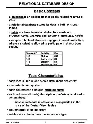
Basic Concepts. a database is an collection of logically related records or files a relational database stores its data in 2-dimensional tables a table is a two-dimensional structure made up of rows ( tuples , records ) and columns ( attributes , fields )

E N D
Basic Concepts • a database is an collection of logically related records or files • a relational database stores its data in 2-dimensional tables • a table is a two-dimensional structure made up of rows (tuples, records) and columns (attributes, fields) • example: a table of students engaged in sports activities, where a student is allowed to participate in at most one activity Table Characteristics • each row is unique and stores data about one entity • row order is unimportant • each column has a unique attribute name • each column (attribute) description (metadata) is stored in the database • Access metadata is stored and manipulated in the rows of the Design View tables • column order is unimportant • entries in a column have the same data type
Primary Keys • a primary key is an attribute, or a collection of attributes whose value(s) uniquely identify each row in a relation • a primary key must be minimal (that is, must not contain unnecessary attributes • we assume that a student is allowed to participate in at most one activity • the primary key in the above table is StudentID • what if we allow the students to participate in more than one activity? • in this table, the two attributes, {StudentID, Activity}, constitute the primary key • a multi-attribute primary key is called a concatenated key, (composite key) and its members are called secondary keys
Foreign Keys • a foreign key is an attribute or a collection of attributes in a relation, whose values match the values of a primary key in some relation • example: the STATE and CITY relations below STATE relation: • primary key in STATE relation: StateAbbrev • primary key in CITY relation: {StateAbbrev, CityName} • foreign key in CITY relation: StateAbbrev
Alternate Database Representations • an alternative representation of the previous database is • STATE = {StateAbbrev, StateName, UnionOrder, StateBird, StatePopulation} • CITY = {StateAbbrev, CityName, CityPopulation} Functional Dependency • a functional dependency is a relationship among attributes • attribute B is functionally dependent on attribute A if given a value of attribute A we can uniquely look up the corresponding value of attribute B • attribute A is the determinant of attribute B if attribute B is functionally dependent on attribute A • in the STATE relation above, StateAbbrev is a determinant of all other attributes, since specifying its value would allow us to determine the values of all other attributes uniquely by table lookup • in the STATE relation, the attribute StateName is also a determinant of all other attributes • in the CITY relation above, the attributes StateAbbrev and CityName together are a determinant of the attribute CityPopulation • in the CITY relation, the attribute CityName is not a determinant of the attribute CityPopulation because multiple cities in the table may have the same name
Functional Dependency Formally, given two attributes A and B, we say that B is functionally dependent on attribute A if ti(A) = tj(A) ti(B) = tj(B) for ij where ti(A) means A’s value in the ith record. Notice that the reverse is not necessarily true. Example: Customer Name is dependent on Customer ID but the reverse is not true assuming that two customers can have the same name.
Dependency Diagrams • a dependency diagram is a pictorial representation of all functional dependencies in a database • an attribute is represented by a rectangle • an arrow is drawn from the rectangle for attribute A to the rectangle for attribute B whenever attribute A is the determinant of attribute B • example: students sports activity - I consists of the relation ACTIVITY = {StudentID, Activity, Fee} StudentID Activity Fee StudentID Activity Fee • example: students sports activity - II consists of the relation ACTIVITY = {StudentID, Activity, Fee}
StudentID Activity Fee StudentID Activity Fee Partial Dependencies • a partial dependency is a functional dependency in which the determinant is a part of the primary key • example: ACTIVITY = {StudentID, Activity, Fee} • the dependency between the attributes Activity and Fee is a partial dependency Transitive Dependencies • a transitive dependency is a functional dependency in which none of the attributes involves attributes of a primary key ( none of them is a part of the primary key) • example: ACTIVITY = {StudentID, Activity, Fee} • the dependency between the attributes Activity and Fee is a transitive dependency
Database Anomalies • anomalies are problems caused by bad database design • problems mean here undesirable irregularities of tables • example: ACTIVITY = {StudentID, Activity, Fee} • an insertion anomaly occurs when a row cannot be added to a relation, because not all data is available • example: we want to store the fact that diving costs $175, but cannot enter this fact into the table until a student takes up scuba-diving • a deletion anomaly occurs when data is deleted from a relation, and unintentionally other critical data are lost • example: by deleting a record (say, StudentID = 100), the fact that skiing costs $200 is lost • an update anomaly occurs when one attribute is changed, but the DBMS must make more than one change to reflect that single change • example: if the cost of swimming changes, then all entries with swimming Activity must be changed too
Cause of Anomalies • anomalies are mostly caused by the following: • data redundancy (replication of the same field in multiple tables) ( repeating sections) • partial dependency • transitive dependency • example: ACTIVITY = {StudentID, Activity, Fee} StudentID Activity Fee • in this example, there is a partial dependency, which the cause of all the anomalies
Cause of Anomalies (Cont.) • a two-table solution: • STUDENTS = {StudentID, Activity} • ACTIVITIES = {Activity, Fee} Fee Activity StudentID Activity • the above relations do not have any of the anomalies • we can add the cost of diving in ACTIVITIES even though no one has taken it in STUDENTS • if StudentID 100 drops Skiing, no skiing-related data will be lost • if the cost of swimming changes, that cost need only be changed in one place only (the ACTIVITIES table) • the Activity field is replicated in the two tables, but without this replication we cannot join the two tables
Good Database Design Principles • 1. no redundancy • a field is stored in only one table, unless it happens to be a foreign key • replication of foreign keys is permissible, because they allow two tables to be joined together • 2.no partial dependencies • the dependency diagram of any relation in the database should contain no partial dependencies • 3.no transitive dependencies • the dependency diagram of any relation in the database should contain no transitive dependencies • normalization is the process of eliminating partial and transitive dependencies • as we normalize the relations, larger tables are split into smaller tables with one common foreign key field • there are five normal forms (NF), as given below First Normal Form (1NF) Second Normal Form (2NF) Third Normal Form (3NF) Boyce Codd Normal Form (BCNF) Fourth Normal Form (4NF) Fifth Normal Form (5NF)
First Normal Form • a relation is said to be in the first normal form (1NF) if it does not contain any nested relation. In other words, all attributes are atomic. • IMPORTANT NOTE: many authors call the nested relations repeating section. This name is missleading. The nested relations involve many different instances of the same attribute for one record. There is nothing repeating in this anomaly. • example: CLIENT table has nested relations. CLIENT = {ClientD, ClientName, VetID, VetName, {PetID, PetName, PetType} }
In order to eliminate the partial dependency, split the table again. • a table is said to be in the second normal form (2NF) if it does not contain any partial dependencies, that is, each nonkey column in a table depends on the entire key. • example: partial dependencies in the relation ClientName Vet Name Client ID VetID transitive PetName Pet Type Client ID PetID • In order to eliminate the nested relation, pull out the nested relation and form a new table • Be sure to include the old key in the new table so that you can connect the tables back together. • When a table contains no nested relations, we say that it is in first normal form. Second Normal Form • now there are no partial dependencies, hence we need not do anything; • the relation still has some anomalies
Client ID Vet Name VetID PetName Client ID Pet Type PetID Third Normal Form • In order to eliminate transitive dependency, we split the table again. • a table of 2NF is said to be in the third normal form (3NF) if it does not contain any transitive dependencies, that is, Each nonkey column depends on the whole key and nothing but the key. • in the 3NF, each determinant is a primary key • example: conversion of CLIENT relation to the 3NF: • CLIENTS = {ClientID, ClientName, VetID} • PETS = {ClientID, PetID, PetName, PetType} • VETS = {VetID, VetName} ClientName VetID • note that the tables can be joined to yield a table in the first normal form • the ClientID and VetID fields are replicated, but they are both foreign keys
Third Normal Form (Cont.) • example: CLIENT database in the third normal form with table relationships • the database consists of three types of entities, stored as distinct relations in separate tables: • clients (CLIENTS) • pets ( PETS) • vets (VETS) • there is no redundancy (only foreign keys are replicated) • there are no partial and transitive dependencies
Example: Hardware Store Database • the ORDERS table :
partial Order Numb Prod Descr Cust Name Prod Price Order Date Cust Code Quantity transitive partial Order Numb Prod Descr Prod Descr Prod Price Quantity transitive Order Numb Cust Name Order Date Cust Code Example: Hardware Store Database (Cont.) • ORDERS = {OrderNumb, ProdDescr, CustCode, OrderDate, CustName, ProdPrice, Quantity} • dependency diagram of the ORDERS table: • conversion of the hardware store database to 2NF • QUANTITY = {OrderNumb, ProdDescr, Quantity} • PRODUCTS = {ProdDescr, ProdPrice} • ORDERS = {OrderNumb, CustCode, OrderDate, CustName} • dependency diagram of the hardware store database in 2NF
Order Numb Prod Descr Prod Descr Prod Price OrderQuant Order Numb Cust Name Order Date Cust Code Cust Code Example: Hardware Store Database (Cont.) • conversion of the ORDERS relation to 3NF • QUANTITY = {OrderNumb, ProdDescr, OrderQuant} • PRICE = {ProdDescr, ProdPrice} • ORDERS = {OrderNumb, CustCode, OrderDate} • CUSTOMERS = {CustCode, CustName} • dependency diagram of the hardware store database in 3NF • table relationships for the hardware store database
Example: Video Store Database • the CUSTOMER relation: • the RENTAL-FORM relation: • a customer can rent multiple videos as part of the same transaction • however, the VideoID fields will be different for each video • multiple copies of the same video are allowed • the copy# field stores the number of the copy • video rental depends on the title and not on the day • the database still contains some anomalies
Customer ID Name Customer ID Rent Date Copy# Rent Example: Video Store Database (Cont.) • relations for the video store database • CUSTOMER = {CustomerID, Phone, Name, Address, City, State, ZipCode} • RENTAL-FORM = {TransID, RentDate, CustomerID, VideoID, Copy#, Title, Rent} • dependency diagram for the video store database Phone City State Address ZipCode Video ID Trans ID Title • video store database after eliminating partial dependencies • CUSTOMER = {CustomerID, Phone, Name, Address, City, State, ZipCode} • RENTALS = {TransID, RentDate, CustomerID} • VIDEOS = {VideoID, Title, Rent} • VideosRented = {TransID, VideoID, Copy#}
Customer ID Trans ID Video ID Copy# Example: Video Store Database (Cont.) • dependency diagram for the video store database in 3NF Name Phone City State Address ZipCode Customer ID Video ID Rent Date Trans ID Title Rent • table relationships for the video store database
Summary of Guidelines for Database Design • identify the entities involved in the database • identify the fields relevant for each entity and define the corresponding relations • determine the primary key of each relation • avoid data redundancy, but have some common fields so that tables can be joined together • ensure that all the required database processing can be done using the defined relations • normalize the relations by splitting them into smaller ones