MATERIALS FOR ELECTRONICS
ELECTRONIC MATERIALS Lecture 04. MATERIALS FOR ELECTRONICS. Applied Electronics Department Technical University of Cluj-Napoca Cluj-Napoca, Cluj, 400027, Romania Phone: +40-264-401412, E-mail: cristian.farcas@ael.utcluj.ro.

MATERIALS FOR ELECTRONICS
E N D
Presentation Transcript
ELECTRONIC MATERIALS Lecture 04 MATERIALS FOR ELECTRONICS Applied Electronics DepartmentTechnical University of Cluj-NapocaCluj-Napoca, Cluj, 400027, RomaniaPhone: +40-264-401412, E-mail: cristian.farcas@ael.utcluj.ro
ELECTRONIC MATERIALS Lecture 04 When atoms combine to form a solid it is the attraction between the positive ion cores and the valence electrons which holds the material together. While the ion cores occupy fixed positions (either in an amorphous or a crystalline structure) the valence electrons whiz around between them, forming a kind of electrostatic glue. In some materials this "glue" is piled up into distinct bonds between particular ion cores (so-called covalent bonding), but in others the electrons are more evenly distributed in the space between the ion cores (known as metallic bonding). A third form of bonding occurs when some of the valence electrons from one atomic species are donated wholesale to another atomic species. Atoms of the species which donates electrons become positive ions and atoms of the species which accepts the electrons become negative ions. This leads to a direct electrostatic attraction between the ions and is known as ionic bonding.
ELECTRONIC MATERIALS Lecture 04 These different forms of bonding are largely responsible for the different thermal and electrical properties of conductors and insulators. Electrical current is transmitted through these solids by the motion of electrons. In a metallically bonded material the electrons can drift easily between the ion cores, but in a covalently bonded material they have to "hop" from one bond to the next in order to move. In an ionically bonded material the valence electrons are tightly bound to ion-cores which are themselves "tied" to fixed ionic sites in the crystal structure. Thus ionic solids are generally poor conductors, covalent solids may be slightly better, and metals are the best of all.
ELECTRONIC MATERIALS Lecture 04 CLASSIFICATION OF MATERIALS CONDUCTORS, INSULATORS, SEMICONDUCTORS • Materials/substances may be classified according to their capacity to carry or conduct electric charge: • Conductors are materials capable of carrying electric current, i.e. material which has “mobile charge carriers” (e.g. electrons, ions,..) • (Copper, aluminum, gold and silver are good conductors. Metallic materials are in general good conductors.) • Insulators are materials with no or very few free charge carriers. • (Glass, quartz, most covalent and ionic solids, plastics are insulators.) • Semiconductors are materials with electrical properties between that of conductors and insulators. • (Germanium Ge, silicon Si, GaAs, GaP, InP are semiconductors used widely in the fabrication of electronic devices.)
ELECTRONIC MATERIALS Lecture 04 Electrical Conductivity σConductors=106-108[S/m] σSemiconductors=10-6-105[S/m] σInsulators=10-7-10-18[S/m] "Solid State Chemistry: An introduction" L. Smart and E. Moore, (Chapman and Hall,1995)
ELECTRONIC MATERIALS Lecture 04 CLASSIFICATION OF MATERIALS CONDUCTORS, INSULATORS, SEMICONDUCTORS • Some representative resistivities (): • R = L/A, R = resistance, L = length, A = cross section area; = resistivity at 20o C • resistivity [m] resistance [] (L=1m, diam =1mm) • aluminum 2.8x10⁻⁸ 3.6x10⁻² • brass 8x10⁻⁸ 10.1x10⁻² • copper 1.7x10⁻⁸ 2.2x10⁻² • platinum 10x10-8 12.7x10⁻² • silver 1.6x10⁻⁸ 2.1x10⁻² • carbon 3.5x10⁻⁵ 44.5 • germanium 0.45 5.7x10⁵ • silicon 640 6x10⁸ • porcelain 1010 - 1012 1016 - 1018 • teflon 1014 1020 • blood 1.5 1.9x10⁶ • fat 24 3x10⁷
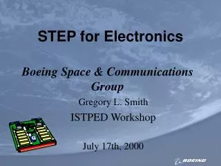
ELECTRONIC MATERIALS Lecture 04 CLASSIFICATION OF MATERIALS Band Theory of Solids A useful way to visualize the difference between conductors, insulators and semiconductors is to plot the available energies for electrons in the materials. Instead of having discrete energies as in the case of free atoms, the available energy states form bands. Crucial to the conduction process is whether or not there are electrons in the conduction band. In insulatorsthere is a large energy gap between the valence and the conduction bands. In conductors, like metals, the valence band overlaps the conduction band, and in semiconductors there is a small energy gap between the valence and conduction bands. With such a small gap, the presence of a small percentage of a doping material can increase conductivity dramatically. An important parameter in the band theory is the Fermi level, the top of the available electron energy levels at low temperatures. The position of the Fermi level with the relation to the conduction band is a crucial factor in determining electrical properties.
ELECTRONIC MATERIALS Lecture 04 Band Theory of Solids Schematic of band structures for (a) insulators, (b) semiconductors, and (c) conductors. (Temperature is 0K.)
ELECTRONIC MATERIALS Lecture 04 Insulator Energy Bands Most solid substances are insulators, and in terms of the band theory of solids this implies that there is a large forbidden gap between the energies of the valence electrons and the energy at which the electrons can move freely through the material (the conduction band). While the doping of insulators can dramatically change their electrical properties. However, the doping of semiconductors has a much more dramatic effect on their electrical conductivity and is the basis for solid state electronics. wI>3eV wF
ELECTRONIC MATERIALS Lecture 04 Semiconductor Energy Bands For intrinsic semiconductors like silicon and germanium, the Fermi level is essentially halfway between the valence and conduction bands. Although no conduction occurs at 0 K, at higher temperatures a finite number of electrons can reach the conduction band and provide some current. In doped semiconductors, extra energy levels are added. wF wI<3eV
ELECTRONIC MATERIALS Lecture 04 Semiconductor Energy Bands Intrinsic Semiconductor A silicon crystal is different from an insulator because at any temperature above absolute zero temperature, there is a finite probability that an electron in the lattice will be knocked loose from its position, leaving behind an electron deficiency called a hole. If a voltage is applied, then both the electron and the hole can contribute to a small current flow. The conductivity of a semiconductor can be modeled in terms of the band theory of solids. The band model of a semiconductor suggests that at ordinary temperatures there is a finite possibility that electrons can reach the conduction band and contribute to electrical conduction. The term intrinsic here distinguishes between the properties of pure "intrinsic" silicon and the dramatically different properties of doped n-type or p-type semiconductors.
ELECTRONIC MATERIALS Lecture 04 Semiconductor Energy Bands Doped Semiconductors The application of band theory to n-type and p-type semiconductors shows that extra levels have been added by the impurities. In n-type material there are electron energy levels near the top of the band gap so that they can be easily excited into the conduction band. In p-type material, extra holes in the band gap allow excitation of valence band electrons, leaving mobile holes in the valence band.
ELECTRONIC MATERIALS Lecture 04 DIELECTRIC MATERIALS Applied Electronics DepartmentTechnical University of Cluj-NapocaCluj-Napoca, Cluj, 400027, RomaniaPhone: +40-264-401412, E-mail: cristian.farcas@ael.utcluj.ro
ELECTRONIC MATERIALS Lecture 04 Dielectric means a non-conductor or poor conductor of electricity. Dielectric means a material that presents electric polarization. Thedielectric is an insulating material or a very poor conductor of electric current. When dielectrics are placed in an electric field, practically no current flows in them because, unlike metals, they have no loosely bound, or free, electrons that may drift through the material. Instead, electric polarization occurs. The positive charges within the dielectric are displaced minutely in the direction of the electric field, and the negative charges are displaced minutely in the direction opposite to the electric field. This slight separation of charge, or polarization, reduces the electric field within the dielectric. The resistivity of insulators is:
ELECTRONIC MATERIALS Lecture 04 If a material contains polar molecules, they will generally be in random orientations when no electric field is applied. An applied electric field will polarize the material by orienting the dipole moments of polar molecules. This decreases the effective electric field between the plates and will increase the capacitance of the parallel plate structure. The dielectric must be a good electric insulator so as to minimize any DC leakage current through a capacitor.
ELECTRONIC MATERIALS Lecture 04 • Applications of dielectric materials: • Dielectrics for capacitors • Insulators • Piezoelectric Transducer • Electrooptic transducer • Temperature transducer • Electret • Theelectret(formed of elektr- from "electricity" and -et from "magnet") is a dielectric material that has a quasi-permanent electric charge or dipole polarisation. An electret generates internal and external electric fields, and is the electrostatic equivalent of a permanent magnet.
ELECTRONIC MATERIALS Lecture 04 The electric properties of dielectrics When a dielectric is introduced in an electric field, two phenomena can be observed: a conduction phenomenon and a polarization phenomenon. The conduction phenomenon consists of the ordered move with respect to the body of some charge carriers. This phenomenon appears because the electric conductivity of the material is different from zero (there are no perfect insulators). The polarization phenomenon consists in the limited movement, under the effect of the electric field, of the electrons and ions; it also consists in the orientation of the polar molecules in the direction of the electric field applied to the polar dielectrics. In the non-homogenous dielectrics it appears an agglomeration of charges on the separation surfaces of their homogenous parts. All these limited movements of charges create the polarization current. The conduction currents and the polarization currents are producing some energy losses in the material. In the DC state, the polarization currents disappear in a very short time after the voltage is applied, and the energy loss is only due to the circulation of the conduction currents. In AC state, there are the polarization currents until the voltage is removed, and the energy loss is due to the circulations of both type of currents (conduction and polarization currents).
ELECTRONIC MATERIALS Lecture 04 The electric properties of dielectrics are related to the phenomena mentioned before, and are: a) The relative dielectric constantεris related to the polarization phenomenon. The relative static permittivity is represented as εror sometimes κ or K or Dk. It is defined as being the ratio between the capacitance of a capacitor having as dielectric the studied material and the capacitance of the same capacitor having vacuum as dielectric. It is also called relative permittivity.
ELECTRONIC MATERIALS Lecture 04 • Measurement: • The relative dielectric constant εr can be measured for static electric fields as follows: first the capacitance of a test capacitor C0 is measured with vacuum between its plates. Then, using the same capacitor and distance between its plates the capacitance CX with a dielectric between the plates is measured. The relative dielectric constant can be then calculated as: • For time-varying electromagnetic fields, the dielectric constant of materials becomes frequency dependent and is generally called permittivity.
ELECTRONIC MATERIALS Lecture 04 • The relative permittivity is a nondimensional number and it has the value: • approximately 1 for gases • 1 – 3 for solids and nonpolar liquids • 3 – 15 for polar solids • tens for polar liquids • hundreds or thousands for ferroelectrics • The permittivity of a material is usually given relative to that of vacuum, as a relative permittivity εr (also called dielectric constant). The actual permittivity is then calculated by multiplying the relative permittivity by ε0: • [F/m] • where χe is the electric susceptibility of the material and
ELECTRONIC MATERIALS Lecture 04 A low-K dielectric is one with a small dielectric constant. In digital circuits, insulating dielectrics separate the conducting parts (wire interconnects and transistors) from one another. To make higher-speed chips, the transistors must be placed closer and closer together, and thus the insulating layer becomes thinner. This leads to charge build up and crosstalk, adversely affecting the maximum operating speed and performance of the chip. Low-K dielectrics have very low dielectric constants, reducing parasitic capacitance and enabling faster switching speeds and lower heat dissipation. The K refers to the dielectric constant. For example the dielectric constant of SiO2, the insulating material used in silicon chips, is 3.9. By doping it with fluorine to produce fluorinated silica glass, this is lowered to 3.5. Another approach is to make a porous dielectric. The pores lead to a smaller average dielectric constant, since air has a dielectric constant of roughly 1.0005.
ELECTRONIC MATERIALS Lecture 04 The term high-κ dielectric refers to materials with a high dielectric constant (κ) which may be used in next generation semiconductor components to replace the silicon dioxide (SiO2) gate dielectric, especially for the low standby power (LSTP) applications. With the continued scaling of the gate oxide to below 2 nm, leakage currents due to tunneling are very high, so the thickness must be increased without reducing the associated capacitance.
ELECTRONIC MATERIALS Lecture 04 From an electrical standpoint, the MOS structure is equivalent to a parallel plate capacitor. When a voltage is applied between the gate and source terminals, the resulting electric field penetrates through the oxide, creating a so-called "inversion channel" within the channel underneath. The inversion channel is of the same type — P-type or N-type — as the source and drain of the transistor, providing a conduit through which current can pass. Ignoring quantum mechanical and depletion effects from the Si substrate and gate, the capacitance C of this parallel plate capacitor is given by Where A is the capacitor area κ is the relative dielectric constant of the material (3.9 for silicon dioxide) ε0 is the permittivity of free space d is the distance between the gate and body
ELECTRONIC MATERIALS Lecture 05 b) The volume resistivityρVand the surface resistivityρS are related to the conduction phenomenon. The volume resistivity is the resistance to leakage current through the body of an insulating material.In SI, volume resistivity is numerically equal to the direct-current resistance between opposite faces of a one-meter cube of the material (Ohm-m). It takes values between 106 and 1018[Ωm] for insulating materials. In practice it is used [Ω cm] (1 Ω cm=10-2 Ω m).
ELECTRONIC MATERIALS Lecture 05 The surface resistivity is determined by the ratio of DC voltage U drop per unit length L to the surface current ISper unit width D. Surface resistivity is a property of a material. Surface resistivity is measured in Ω. The current doesn't pass through the material, only through the surface of the material. The thickness of the layer (and ρS) depends on the chemical composition, on the structure of the material, on the impurities, on the processing degree of the material, on the humidity, etc. For insulating materials ρs= 108÷1018[Ω].
ELECTRONIC MATERIALS Lecture 05 c) The Dielectric Loss Factor(ordielectric dissipation factor) – tan δ –is related both to the conduction phenomena and to the electric polarization. The dielectric lossfactorcharacterizes the total energy loss from the dielectric. The dielectric loss angle of an insulating material is the difference between ninety (90°) degrees and the dielectric phase angle.
ELECTRONIC MATERIALS Lecture 05 The dielectric loss angle: δ = 90-φ represents the complement of the phase angle between the applied voltage U and the total current I (only between the active current IAand the capacitive one IC) that flows through the dielectric.
ELECTRONIC MATERIALS Lecture 05 The dielectric dissipation factor (tan δ) of an insulating material is the tangent of the loss angle δ. In a perfect dielectric, the voltage wave and the current are exactly 90° out of phase. As the dielectric becomes less than 100% efficient, the current wave begins to lag the voltage in direct proportion. The amount the current wave deviates from being 90° out of phase with the voltage is defined as the dielectric loss angle. The tangent of this angle is known as the loss tangent or dissipation factor.A low dissipation factor is important for plastic insulators in high frequency applications such as radar equipment and microwave parts; smaller values mean better dielectric materials. A high dissipation factor is important for welding capabilities. Both relative permittivity and dissipation factor are measured using the same test equipment. Test values obtained are highly dependent on temperature, moisture levels, frequency and voltage.
ELECTRONIC MATERIALS Lecture 05 d) The dielectric strength(ESTR) is the minimum electric field that produces breakdown. The dielectric strength is given by the ratio between the breakdown voltage (USTR) and the thickness (d) of the material between the electrodes. Breakdown Voltage (Insulator) Is a parameter of an insulator that defines the maximum voltage difference that can be applied across the material before the insulator collapses and conducts. This may create a weak point in the insulator from a molecular change created by the current flow. Two different breakdown voltage measurements of a material are the AC and impulse breakdown voltages. The AC voltage is the line frequency of the mains (either 50 or 60 Hz depending on where you live). The impulse breakdown voltage is simulating lightning strikes, and uses a 1.2 microsecond rise for the wave to reach 90% amplitude then drops back down to 50% amplitude after 50 microseconds.
ELECTRONIC MATERIALS Lecture 05 APPLICATIONS OF DIELECTRIC MATERIALS When an electric field is applied to a dielectric medium, a current flows. The total current flowing in a real dielectric has two parts: a conduction and a displacement current. The displacement current can be considered the elastic response of the dielectric material to the applied electric field. As the magnitude of the electric field is increased, the additional displacement is stored as potential energy within the dielectric. When the electric field is decreased, the dielectric releases some of the stored energy as a displacement current. The electric displacement can be separated into a vacuum contribution and one arising from the dielectric by where D and E are the amplitudes of the displacement and electrical fields,P is the polarization of the medium and χ its electric susceptibility. It follows that the relative permittivity and susceptibility of a dielectric are related,
ELECTRONIC MATERIALS Lecture 05 1. Dielectrics in Capacitors A dielectric material placed between the plates of a parallel plate capacitor causes an increase in the capacitance in proportion to the relative permittivity of the material: This happens because an electric field polarizes the molecules of the dielectric, producing concentrations of charge on its surfaces that create an electric field opposed (antiparallel) to that of the capacitor. Thus, a given amount of charge produces a weaker field between the plates than it would without the dielectric, which reduces the electric potential. Considered in reverse, this argument means that, with a dielectric, a given electric potential causes the capacitor to accumulate a larger charge polarization.
ELECTRONIC MATERIALS Lecture 05 In AC, the relative permittivity of the material isn’t a scalar constant. D and E are the amplitudes of the displacement and electrical fields in complex representation. The admittance of capacitor is:
ELECTRONIC MATERIALS Lecture 05 If the dielectric substance between a capacitor's plates is not a perfect insulator, there will be a path for direct current (DC) from one plate to the other. This is typically called leakage resistance, and it is modeled as a shunt resistance to an ideal capacitance.
ELECTRONIC MATERIALS Lecture 05 The Dielectric Loss Factor (or dielectric dissipation factor) is related both to the conduction phenomena and to the electric polarization. The dielectric lossfactorcharacterize the total energy loss from the dielectric. The Dielectric Loss Factor is defined by relation: The Q factor or quality factor is the inverse of the dissipation factor (tan δ).
ELECTRONIC MATERIALS Lecture 05 2. Electrical Insulator An insulator is a material or object which contains no movable electrical charges. When a voltage is placed across an insulator, no charges flow, so no electric current appears. The term electrical insulator has the same meaning as the term dielectric, but the two terms are often used in different contexts. Very pure semiconductors are insulators at low temperatures unless doped with impurity atoms that release extra charges which can flow in a current. A few materials (such as silicon dioxide) are almost ideal electrical insulators, a property that is invaluable in flash memory technology. Teflon is another almost ideal insulator, making it a valuable material for long term charge storage in electrets. A much larger class of materials, for example rubber and most plastics are still "good enough" to insulate electrical wiring and cables even though they may have lower bulk resistivity. These materials can serve as practical and safe insulators for low to moderate voltages (hundreds, or even thousands, of volts).
ELECTRONIC MATERIALS Lecture 05 3. Piezoelectric Transducer Piezoelectricity is the ability of crystals to generate a voltage in response to applied mechanical stress. The word is derived from the Greek piezein, which means to squeeze or press. The piezoelectric effect is reversible in that piezoelectric crystals, when subjected to an externally applied voltage, can change shape by a small amount. (For instance, the deformation is about 0.1% of the original dimension in PZT.) The effect finds useful applications such as the production and detection of sound, generation of high voltages, electronic frequency generation, microbalance, and ultra fine focusing of optical assemblies.
ELECTRONIC MATERIALS Lecture 05 Piezoelectric sensor The principle of operation of a piezoelectric sensor is that a physical dimension, transformed into a force, acts on two opposing faces of the sensing element. Depending on the design of a sensor, different "modes" to load the piezoelectric element can be used: longitudinal, transversal and shear. To detect sound, e.g. piezoelectric microphones (sound waves bend the piezoelectric material, creating a changing voltage) and piezoelectric pickups for electrically amplified guitars. A piezo sensor attached to the body of an instrument is known as a contact microphone. Piezoelectric elements are also used in the generation of sonar waves. Piezoelectric microbalances are used as very sensitive chemical and biological sensors. Piezoelectric transducers are used in electronic drum pads to detect the impact of the drummer's sticks. Automotive engine management systems use a piezoelectric transducer to detect detonation, by sampling the vibrations of the engine block.
ELECTRONIC MATERIALS Lecture 05 Piezoelectric Actuators As very high voltages correspond to only tiny changes in the width of the crystal, making piezo crystals the most important tool for positioning objects with extreme accuracy — thus their use in actuators. Loudspeakers: Voltages are converted to mechanical movement of a piezoelectric polymer film. Piezoelectric motors: piezoelectric elements apply a directional force to an axle, causing it to rotate. Due to the extremely small distances involved, the piezo motor is viewed as a high-precision replacement for the stepper motor. Inkjet printers: On some high-end inkjet printers, piezoelectric crystals are used to control the flow of ink from the cartridge to the paper. Ultrasonic transducers Piezoelectric materials are used as ultrasonic transducers for imaging applications (e.g. medical imaging, industrial nondestructive testing, or NDT) and high power applications (e.g. medical treatment, sonochemistry and industrial processing). For imaging applications, the transducer can act as both a sensor and an actuator. Ultrasonic transducers can inject ultrasound waves into the body, receive the returned wave, and convert it to an electrical signal (a voltage). Most medical ultrasound transducers are piezoelectric.
ELECTRONIC MATERIALS Lecture 05 4. Electro-optic Transducer The electro-optic effect is a change in the optical properties of a material in response to an electric field that varies slowly compared with the frequency of light. Electro-optic modulators are usually built with electro-optic crystals exhibiting the Pockels effect. The transmitted beam is phase modulated with the electric signal applied to the crystal. Amplitude modulators can be built by putting the electro-optic crystal between two linear polarizers. Liquid crystals find wide use in liquid crystal displays, which rely on the optical properties of certain liquid crystalline molecules in the presence or absence of an electric field. In a typical device, a liquid crystal layer sits between two polarizers that are crossed (oriented at 90° to one another). The liquid crystal is chosen so that its relaxed phase is a twisted one. This twisted phase reorients light that has passed through the first polarizer, allowing it to be transmitted through the second polarizer and reflected back to the observer.
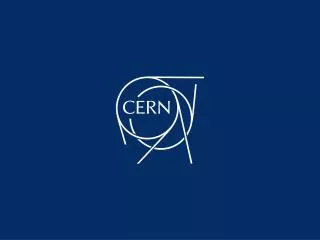
ELECTRONIC MATERIALS Lecture 05
ELECTRONIC MATERIALS Lecture 05 • Reflective twisted nematic liquid crystal display. • Vertical filter film to polarize the light as it enters. • Glass substrate with ITO electrodes. The shapes of these electrodes will determine the dark shapes that will appear when the LCD is turned on or off. Vertical ridges etched on the surface are smooth. • Twisted nematic liquid crystals. • Glass substrate with common electrode film (ITO) with horizontal ridges to line up with the horizontal filter. • Horizontal filter film to block/allow through light. • Reflective surface to send light back to viewer. Indium tin oxide (ITO, or tin-doped indium oxide) is a mixture of indium(III) oxide (In2O3) and tin(IV) oxide (SnO2), typically 90% In2O3, 10% SnO2 by weight. It is transparent and colorless in thin layers.
ELECTRONIC MATERIALS Lecture 07 5. Pyroelectric Transducer Pyroelectricity is the ability of certain materials to generate an electrical potential when they are heated or cooled. As a result of this change in temperature, positive and negative charges move to opposite ends through migration (i.e. the material becomes polarised) and hence, an electrical potential is established. Although artificial pyroelectric materials have been engineered, the effect was first discovered in minerals such as quartz and tourmaline and other ionic crystals. The name is derived from the Greek pyr, fire, and electricity. Pyroelectric charge in minerals develops on the opposite faces of asymmetric crystals. The direction in which the propagation of the charge tends toward is usually constant throughout a pyroelectric material, but in some materials this direction can be changed by a nearby electric field. These materials are said to exhibit ferroelectricity. All pyroelectric materials are also piezoelectric, the two properties being closely related. Very small changes in temperature can produce an electric potential due to a materials' pyroelectricity. Motion detection devices are often designed around pyroelectric materials, as the heat of a human or animal from several feet away is enough to generate a difference in charge.
ELECTRONIC MATERIALS Lecture 07 6. Electret Electret (formed of elektr- from "electricity" and -et from "magnet") is a dielectric material that has a quasi-permanent electric charge or dipole polarisation. An electret generates internal and external electric fields, and it is the electrostatic equivalent of a permanent magnet. Electrets are only in a metastable state, but may still store excess charge or polarization for extremely long periods of time. Manufacture Bulk electrets can be prepared by cooling a suitable dielectric material within a strong electric field, after heating it above its melting temperature. The field repositions the charge carriers or aligns the dipoles within the material. When the material cools, solidification freezes them in position. Materials used to for electrets are usually waxes, polymers or resins.
ELECTRONIC MATERIALS Lecture 07 Electret materials have recently found commercial and technical interest. For example, they are used in electrostatic microphones and in copy machines. They are also used in some types of air filters, for electrostatic collection of dust particles, and in electret ion chambers for measuring ionizing radiation. An electret microphone is a relatively new type of condenser microphone, which eliminates the need for a high-voltage bias supply by using a permanently-charged material.
ELECTRONIC MATERIALS Lecture 07 ELECTRICAL CONDUCTION Electrical conduction is the movement of electrically charged particles through a transmission medium. The movement of charge constitutes anelectric current in response to an electric field. The physical parameters governing this transport depend upon the material. Conduction is well-described by Ohm's Law, which states that the current is proportional to the applied electric field. The ease with which current density (current per area) j appears in a material is measured by the conductivity σ, defined as:
ELECTRONIC MATERIALS Lecture 07 1. Electrical Conduction of Insulating Solids Materials in which all energy bands are full (i.e. the Fermi energy is between two bands) are insulators. Bands which are completely full of electrons cannot conduct electricity, because there is no state of nearby energy to which the electrons can jump. If the crystal is with impurities, in the band gap of insulating material the extra levels have been added by the impurities. The electrical conduction in insulating solids is given by the intrinsic conduction and by the extrinsic conduction. If the insulating material is very pure, the electrical conduction is insignificant.
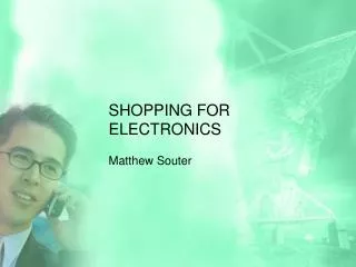
ELECTRONIC MATERIALS Lecture 07 The variation of the electric conductivity of an insulating crystal with the intensity of electric field.
ELECTRONIC MATERIALS Lecture 07 1. In the usual electric fields (E<105-106V/m), the ionic conduction is predominant, and the total conductivity (σt), practically it does not depend on the intensity of the electric field. This domain is called Ohm’s interval. The ionic conduction of the insulating crystals is realized through the convection of the interstitial own ions (resulting by Frenkel defects), by the convection of the vacancies (resulting by Frenkel defects or Schottky defects), or through the convection of the impurities ions (from the nodes or interstices). The electronic conduction is realised like in the case of extrinsic semiconductor, through the convection of the electrons that reached the conduction band from the donor level or from the valence band and through the convection of the holes from the valence band.
wh ELECTRONIC MATERIALS Lecture 07 The band structure for insulators with impurities.
ELECTRONIC MATERIALS Lecture 07 The electronic conductivity (σel)is the sum of the intrinsic conductivity (σi) and the extrinsic conductivity given by electrons (σe) and by holes (σh). Where Ci, Ce and Ch are constants and don’t depend by the time and by the electric field’s intensity. Ce and Ch are dependent by the number of extra levels (they are proportional with the concentration of the impurities).