Download
1 / 13
130 likes | 151 Vues
Gas-filled capillary discharge waveguides for laser-plasma interaction. Overview, channel formation, and guiding with square capillaries. Detailed analysis of limitations, mechanisms, and guiding experiments.

E N D
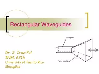
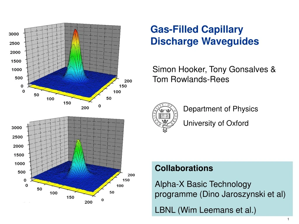
Gas-Filled Capillary Discharge Waveguides Department of Physics University of Oxford Simon Hooker, Tony Gonsalves & Tom Rowlands-Rees Collaborations Alpha-X Basic Technology programme (Dino Jaroszynski et al) LBNL (Wim Leemans et al.)
Limitations to the laser-plasma interaction length • Spot size: • 1/e2 radius in intensity • Diffraction • Refraction • For partially ionized plasmas refraction further limits the interaction length • Diffraction limits the interaction length to the order of the Rayleigh range: • Example: W0 = 10 µm; = 1 µm • ZR = 0.3 mm
Gradient refractive index guiding - Plasma waveguides • For non-relativistic intensities the refractive index of a plasma may be written: • Hence a parabolic electron density profile: • supports matched guiding of Gaussian beams with a constant spot size:
Channels laser machined in sapphire blocks Channel 200 - 400 μm diameter Gas injected near each end of channel Gas-filled capillary discharge waveguide: Overview D. J. Spence et al. Phys. Rev. E63 015401(R) (2001) • Gas ionized by pulsed discharge • Peak current 100 - 500 A • Rise-time 50 - 100 ns
Channels laser machined in sapphire blocks Channel 200 - 400 μm diameter Gas injected near each end of channel Gas-filled capillary discharge waveguide: Overview D. J. Spence et al. Phys. Rev. E63 015401(R) (2001) • Gas ionized by pulsed discharge • Peak current 100 - 500 A • Rise-time 50 - 100 ns
Mechanism of Channel Formation – MHD Simulation • Bobrova et al. Phys. Rev. E65 016407 (2001) • No pinch effect is observed • Plasma fully ionized for t > 50 ns • Ablation of capillary wall found to be negligible
Mechanism of Channel Formation – MHD Simulation • Bobrova et al. Phys. Rev. E65 016407 (2001) • Discharge reaches a quasi equilibrium in which Ohmic heating of plasma is balanced by conduction of heat to wall: • Solution of the heat flow equation yields a scaling relation for the matched spot size:
Guiding With Square Capillaries Transmission = 90% t = 115 ns Guided spot 27 × 32 µm • 33 mm long, 400 μm square capillary • 120 mbar H2 • Transmitted spots ~ same size as input spot
Guiding With Square Capillaries (a) Input intensity 5.8 1016 W cm-2;W ~28μm (b) Exit: Unguided Output Spot t <0ns (c) Exit t =115ns
Energy Meter Laser OAP Wedges Capillary Waveguide Spectrometer Energy meter Guiding experiments at LBNL (preliminary results) Guiding at 15 TW 50 μm input spot I ~ 5 ×10¹⁷ Wcm-2 Beam 33 mm after focus (no waveguide) Beam at exit of 33 mm long waveguide I ~ 5 ×10¹⁷ Wcm-2
Nd:YAG camera 1.2 1.1 1.0 0.9 0.8 0.7 Electron Density (1018 cm-3) Position in Capillary Transverse interferometry 60 mbar 140 ns
Scaling of matched spot size • Matched spot scales as • However the optimum coupling for grazing-incidence guiding is, Plasma waveguide Grazing-incidence waveguide
Summary • Advantages • Guiding of laser pulses with peak intensities of ~ 5 × 10¹⁷ Wcm-2 over 33 mm demonstrated • High pulse energy and peak intensity transmission • Low coupling losses • Long device lifetime demonstrated • Should be able to be staged • Disadvantages • Guided spot size relatively large (> 20 µm) • Spot size becomes even larger at low plasma densities