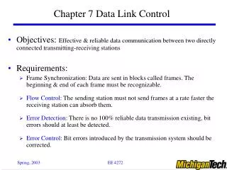

Efficient Data Link Control Protocols for Business Data Communications
E N D
Presentation Transcript
Chapter 9:Data Link Control Business Data Communications, 4e
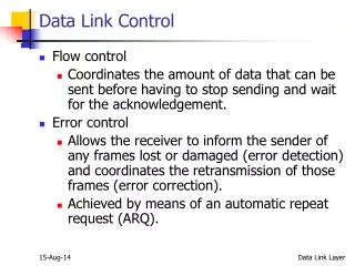
Flow Control • Necessary when data is being sent faster than it can be processed by receiver • Computer to printer is typical setting • Can also be from computer to computer, when a processing program is limited in capacity
Stop-and-Wait Flow Control • Simplest form • Source may not send new frame until receiver acknowledges the frame already sent • Very inefficient, especially when a single message is broken into separate frames, or when the data link is long enough for significant delays to be introduced
Sliding-Window Flow Control • Allows multiple frames to be in transit • Receiver sends acknowledgement with sequence number of anticipated frame • Sender maintains list of sequence numbers it can send, receiver maintains list of sequence numbers it can receive • ACK (acknowledgement) supplemented with RNR (receiver not ready)
Error Control Process • All transmission media have potential for introduction of errors • All data link layer protocols must provide method for controlling errors • Error control process has two components • Error detection • Error correction
Error Detection: Parity Bits • Bit added to each character to make all bits add up to an even number (even parity) or odd number (odd parity) • Good for detecting single-bit errors only • High overhead (one extra bit per 7-bit character=12.5%)
Error Detection: Cyclic Redundancy Check (CRC) • Data in frame treated as a single binary number, divided by a unique prime binary, and remainder is attached to frame • 17-bit divisor leaves 16-bit remainder, 33-bit divisor leaves 32-bit remainder • For a CRC of length N, errors undetected are 2-N • Overhead is low (1-3%)
Error Correction • Two types of errors • Lost frame • Damaged frame • Automatic Repeat reQuest (ARQ) • Error detection • Positive acknowledgment • Retransmission after time-out • Negative acknowledgment and retransmission
Stop-and-Wait ARQ • One frame received and handled at a time • If frame is damaged, receiver discards it and sends no acknowledgment • Sender uses timer to determine whether or not to retransmit • Sender must keep a copy of transmitted frame until acknowledgment is received • If acknowledgment is damaged, sender will know it because of numbering
Fig. 9.5 (Page 217)
Go-Back-N ARQ • Uses sliding-window flow control • When receiver detects error, it sends negative acknowledgment (REJ) • Sender must begin transmitting again from rejected frame • Transmitter must keep a copy of all transmitted frames
Data Link Control • Specified flow and error control for synchronous communication • Data link module arranges data into frames, supplemented by control bits • Receiver checks control bits, if data is intact, it strips them
High-Level Data Link Control • On transmitting side, HDLC receives data from an application, and delivers it to the receiver on the other side of the link • On the receiving side, HDLC accepts the data and delivers it to the higher level application layer • Both modules exchange control information, encoded into a frame
Flag: 01111110, at start and end Address: secondary station (for multidrop configurations) Information: the data to be transmitted Frame check sequence: 16- or 32-bit CRC Control: purpose or function of frame Information frames: contain user data Supervisory frames: flow/error control (ACK/ARQ) Unnumbered frames: variety of control functions (see p.222) HDLC Frame Structure
8-bit Control Field Refer to Table 9.1 (Page 222)
HDLC Operation • Initialization: S-frames specify mode and sequence numbers, U-frames acknowledge • Data Transfer: I-frames exchange user data, S-frames acknowledge and provide flow/error control • Disconnect: U-frames initiate and acknowledge