Modular Coil Assembly Fixture (MCAF)
Modular Coil Assembly Fixture (MCAF). Peer Review February 16, 2005. T. Brown. Agenda. Define the basic design intent Describe the Reference Design used to generate design specifications. Review design Issues: kinematics, bolt access, CG location, seismic, safety. . .

Modular Coil Assembly Fixture (MCAF)
E N D
Presentation Transcript
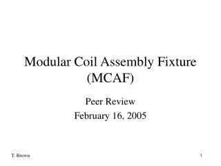
Modular Coil Assembly Fixture(MCAF) Peer Review February 16, 2005 T. Brown
Agenda • Define the basic design intent • Describe the Reference Design used to generate design specifications. • Review design Issues: • kinematics, bolt access, CG location, seismic, safety. . . • Discuss upcoming information meeting
Design Intent: • Rotate module coil half period over the vacuum vessel • Join two MC half periods at their precise “winding” position
A 1.76" (metal-to-metal) min clearance between MC’s and VV. VV insulation is 1.0” and VV/MC nominal tolerances are 0.06”.
A .45” minimum clearance exists between the Type A’s as the two half period MC shells comes together.
. Y X Z The motion of the MC over the VV was controlled by six axis following Art’s data transformed with a 6.125” X-axis vertical shift. Z Rz Rx X X Ry
MCAF motion is based on a 248 step servo table to drive the six motors.
In their final position two modular coil half periods will be separated by 0.50” (nominally) with three spherical seats engaged within an accuracy of 0.009”. . . If all goes well. Leica laser system used for assembly measurement.
C5 B5 A5 C4 A6 B4 B6 A4 C6 A3 C1 B3 B1 C3 A1 C2 B2 A2 Half Period Assembly Sequence – perform all alignment and hole placement at this stage.
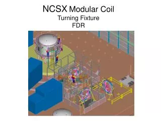
Gantry Crane Module Coil Half Period Module Coil Half Period Turning Fixture Base Guide Rail MCAF Reference Design The Reference Design was develop to qualify technical feasibility and help in establishing a design specification.
MCAF Component Details Module Coil Half Period (25000 lbs max) MCHP / Turning Fixture interface Pivot and rotation component (3200 lbs) Cradle component (6300 lbs) Vertical guide component (3500 lbs) 18,700 lbs (2700 lbs) Linear turntable structure Linear motion structure (3000 lbs)
RY = 13° RX = 5° DZ = 16” RZ = 15° DX = 12” Z Y X Defined extent of motion of turning fixture subcomponents. DY = 140”
0.54” 74” 82” Typically ½ HP Motors with 200 : 1 reducers drive mechanical screws, screw jacks and gears For movement in “Y” direction: Assume 1750 rpm motor with 200:1 reducer & 0.25 screw lead 1 3 2 @ 1750 rpm – 2.2”/min 1 Travel time – 33.3 min @ 1200 rpm – 1.5”/min 2 Travel time – 54.7 min @ 500 rpm – .625”/min 3 Travel time – .86 min
Sideways clearances between MC shell and secondary support structure shall be greater that 60”
Half Period Bolt Access – accessible on top and outside – more restrictive in reaching the lower, inside bolts. A 40” local platform required
34.8’ 21.25’ Test cell assembly space requirements.
With rotational extraction of the completed Period the required test cell assembly space can be reduced. 63” potential space savings.
What seismic design criteria do you apply during an assembly process? • 30 days is the schedule time to complete the half period assembly operation. • 5 days are allocated to secure one HP by the gantry crane, and as noted earlier one successful run takes a minimum of 1.5 hrs. If a seismic design criteria is needed does a dynamic magnification factor of 0.12 apply?
The red curve defines the path of the MCHP CG as the assembly fixture moves from a starting position just outside the VV to it final position. final position starting position
Starting Position - CG Locations (Base End and Front Views) 18,300 MCFP 38,000 MCAF
89.1” Starting Position - CG Locations (End and Top Views from Vertical Guide Structure) 18,300 MCHP 38,000 MCAF
Final Position - CG Locations (Front and Top Views from Base Structure) 18,300 MCHP 38,000 MCAF 100.0”
Side view shows worst seismic position • The existing base will work with captured rollers and a .12 DMF. • Values above .16 will require an expanded base. 4560 lbs (assumes a .12 DMF) 38,000 lbs 104” 34”
Very preliminary stress analysis of the gantry crane and assembly fixture have been generated at this time. Load = 23,000 lbs
Max stress = 11 ksi Max Disp = .09 in Load = 23,000 lbs Total Unit weight = 36,410 lbs
Vendor List Five vendors have expressed interest in the MCAF fabrication at this time. - Hilman Rollers - Sissco Control - three others? A vendor information meeting is scheduled for 9 AM Wednesday, February 23.