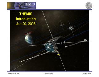
THEMIS Introduction Jan 29, 2008
360 likes | 529 Vues
THEMIS Introduction Jan 29, 2008. Agenda. Agenda Mission Objectives Organization Schedule Mission Implementation S/C & Instrument Description Ground Systems Mission Operations. Substorms. Earth and Space Platforms. Aurora. Current disruption. Reconnection. Organization.

THEMIS Introduction Jan 29, 2008
E N D
Presentation Transcript
THEMIS • Introduction • Jan 29, 2008
Agenda • Agenda • Mission Objectives • Organization • Schedule • Mission Implementation • S/C & Instrument Description • Ground Systems • Mission Operations
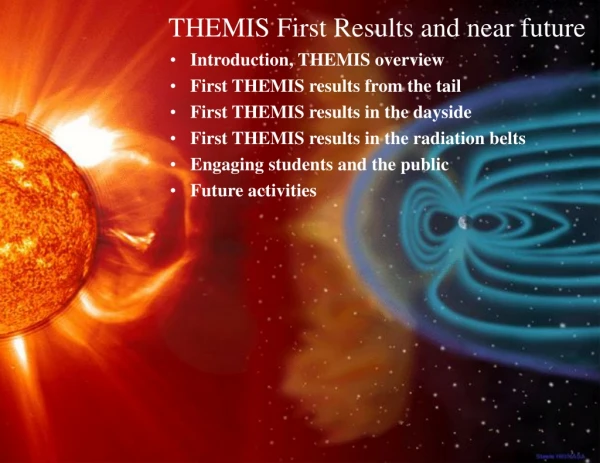
Earth and Space Platforms Aurora Current disruption Reconnection
Organization • Program Organization • PI Mode PI Team Provides Space, Ground, Data Segments PI Team Provides Cost, Schedule, Performance Assurance PI Team Provides Education/Public Outreach • Cost and Schedule Caps Single Cost Cap for the Mission $180M (FY07) Launch no later than March 2007 (Launch Feb 2007) • Performance Assurance MIDEX Quality Requirements • Implementation Strategy Use Heritage Instrumentation Coordinate Common Buy Parts Keep Probe/Probe Carrier Simple and Robust Leave Complexity on the Ground Build & Verify Probe 1, then Probes 2-5
Mission Manager Frank Snow, GSFC Project Scientist D. Sibeck, GSFC Launch Vehicle G. Skrobott, KSC THEMIS PI V. Angelopoulos, UCB Science Co-I’s EPO N. Craig, UCB Project Manager P. Harvey, UCB Quality Assurance R. Jackson, UCB Scheduling D. Meilhan, UCB Financial Mgr K. Harps, UCB Subcontracts J. Keenan, UCB Mechanical/ Thermal Systems P. Turin, UCB C. Smith, UCB Mission Systems E. Taylor, UCB Probe/Probe Carrier Management UCB Oversight: D. King Swales Mgr: M. Cully Instruments P. Berg, UCB Software Systems D. King, UCB Mag Cleanliness C. Russell, UCLA Mission I&T J. McCauley, UCB R. Sterling, UCB Operations M. Bester, UCB Organization
Instruments P. Berg Instrument Data Processor Unit (IDPU) M. Ludlam Electric Field Instrument (EFI) J. Bonnell Electrostatic Analyzer (ESA) C. Carlson Solid State Telescope (SST) D. Larson Fluxgate Mag (FGM) U. Auster Search Coil Mag (SCM) A. Roux Robert Abiad Peter Berg Heath Bersch Dorothy Gordon Selda Heavner Jim Lewis Jeanine Potts Nestor Castillo Forrest Mozer Greg Delory Art Hull Bill Donakowski Greg Dalton Robert Duck Dan Schickele Stu Harris Hilary Richard C. Scholz M. Marckwardt Bill Elliott Heath Bersch Ron Canario Robert Lee T. Moreau TUBS/IWF Uli Auster K. Glassmeier W. Magnes CETP Alain Roux Bertran de la Porte Olivier Le Contel Christophe Coillot A. Bouabdellah Mag Booms LASP Robert Ergun Aref Nammari Ken Stevens Jim Westfall Hari Dharan Tien Tan Bill Tyler Organization
Organization Ground Segment Mission Ops Science Ops Flight Dynamics Ground Based Observatories All Sky Imagers Ground Magnetometers Fielding & Operation (UC&UA) Manfred Bester Mark Lewis Tim Quinn Sabine Frey Tai Phan Stephen Mende Stu Harris Harald Frey UCLA Chris Russell Joe Means Dave Pierce Bob Snare UC Eric Donovan GSFC/GCND David Sibeck Mark Beckman Bob DeFazio Rick Harman UA J. Samson
Mission Overview Launch Vehicle: Delta II, Eastern Range Apogee: 91845.2 km ± 9567 km Perigee: 435 km ± 10 km (500 km ± 7 km on or after 3/1/2007) Inclination: 16.0 deg ± 0.5 deg Date: February 17, 2007 Space Segment Spacecraft: 5 Spinning Probes with Fuel for Orbit & Attitude Adjust Instruments: 3-Axis Electric Field, Magnetic Field 3-D Ion & Electron Particle Detectors Spin Rate: 20 RPM Orbit Period(s): 1, 2 and 4 days Orientation: Ecliptic Normal Ground Segment Observatories: 20 Northern with All Sky Imagers and Magnetometers Control Facilities: Mission and Science Operations Centers Operations Phases: L&EO, Cruise, Ascent, Campaigns, De-orbit Lifetime: 2.5 years
Instrument Configuration IDPU: Instrument Data Processor Unit SPB : Spin Plane Booms (4x) AXB : Axial Booms (2x) SST : Solid State Telescope (2x) ESA : Electrostatic Analyzer FGM : Fluxgate Magnetometer SCM : Search Coil Magnetometer
Probe Configuration Antenna EFI Axial Booms (2, Stowed) ESA Miniature Sun Sensor Fuel Tank IDPU EFI SPB Repress Tank Transponder Fuel Tank Thruster A2 Thruster T1 EFI SPB Thruster A1 BAU Battery Gyros EFI SPB Thruster T2 AEB 11
Mission Data Flows THEMIS Probe TDRS Berkeley Ground Station Wallops Ground Station KSC & Astrotech Merritt Island Ground Station (1) (3) Compatibility Test Van JPL I&T Facility UCB I&T Facility (3) White Sands Complex (3) Secure Intranet Santiago Ground Station Secure VPN Tunnel via Open Internet (2) GSFC NMC Open IONet Dial-up ISDN Line Berkeley Mission Operations Center Notes: Open (1), Restricted (2) or Closed (3) IONet Hartebeesthoek Ground Station Different Routes for End-to-end Data Flows Between Probes and GS Elements
Geographic Longitude 195° Geographic North Pole Geographic Longitude 324° Geomagnetic NorthPole Courtesy H.Frey, UCB Ground Based Observatories • Ground Based Observatories • UCB/UCLA Delivered All 20 GBO (GMAG and ASI) units • Automatic Data Collection and Archiving in Progress • Remote Commanding and Diagnostics Working
Ground Based Observatories GBO Sites EPO Sites
Probe 2 I&T F2 I&T at UCB Magnetics at JPL EMC at JPL VIB at JPL TV at JPL Probe Fit Check
Probes 1,3,4,5 I&T FM4/5 in Thermal Vac Bus Assembly Probe I&T FM2/FM3 Thermal Vacuum
JPL2 PCA Buildup • PCA Assembly and Test
JPL2 Environments Acoustics & Shock Vibration Spin Balance Thermal Vacuum FM2/FM3 Thermal Vacuum Storage
ASO Probe Processing Delivery to ASO Bolt Cutter Installation Solar Array Illumination Performance Tests
ASO Probe Fueling Vibration Acoustics Spin Balance Dry Weigh & Pressurize Fueling Thermal Vacuum Storage
ASO PCA Processing Final checks Acoustics Spin Balance PCA Integration SSS Installation Ready for Probes Vibration Fairing Installation Storage Spin Balance
Ground Based Observatories Production line @ UCB Fort Yukon, AK, site GMAG ASI EPO GMAG
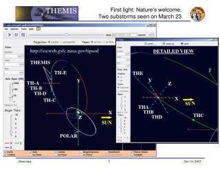
Orbit Plans Coast http://sscweb.gsfc.nasa.gov/tipsod/ Placement Tail 1 http://sscweb.gsfc.nasa.gov/tipsod/
Probe Placement Decision • Probe Placement Decision • Assigned Constellation IDs (P1−P5) to Probe Buses THEMIS A −> P5 THEMIS B −> P1 THEMIS C −> P2 THEMIS D −> P3 THEMIS E −> P4 • Decision Based on Probe Bus and Instrument Performance • Also Included Performance Details Found During Ground Testing • Only Differences Noted Are in Telecom System • Team Members Involved in Probe Placement Decision • PI, PM, MSE, MOM, MDL, Swales Probe Bus Systems Lead, Instrument Scientists, GSFC Program Manager and GSFC Project Scientist
Year at a Glance Predicted conjunctions exceed 188hrs/season with ~50% margin
Inst Status • Instrument Status Charts (5 Flight & Spare)
PFR Tracking • PFR Status Charts (vs. 5 Flight & Spare)
PFR Statistics • PFR Statistics Coverage • Instrument I&T • Probe-Instrument I&T • Environments thru Launch • Sequence of Events • Probe Bus A flow halted at Swales • Probe Bus B, Inst B integrated first • Completed Probe B before Integrating the rest • Sequence: B-CDEA or 2-3451
Top Problems Bus I&T Probe 1 Deck Fabrication Problems (3x) Bus I&T Probe 1 RCS Pressure Transducer Bus I&T Overall Schedule Probe I&T All BAU Sockets Showed Damage Probe I&T All Transponders Built with Pure Tin Lugs Probe I&T All Transponders Filter Modification Required Probe I&T All Diplexors Mod for Vib Failure, Venting Modification and Retest Environments Probe 2 Fuel Line Backup thermostat near spec Environments All EFI Axial Boom Covers Contaminated Pre-Launch All EFI Preamp Capacitors Needed Replacement