Subroutines
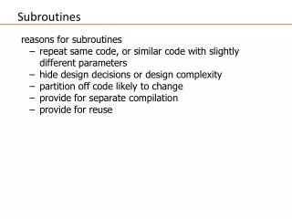
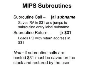
Subroutines. A subroutine is a block of code that is called from different places from within a main program or other subroutines. Saves code space in that the subroutine code does not have to be repeated in the program areas that need it; only the code for the subroutine call is repeated.

Subroutines
E N D
Presentation Transcript
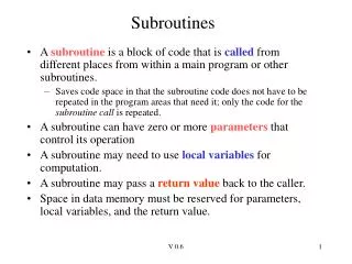
Subroutines • A subroutine is a block of code that is called from different places from within a main program or other subroutines. • Saves code space in that the subroutine code does not have to be repeated in the program areas that need it; only the code for the subroutine call is repeated. • A subroutine can have zero or more parameters that control its operation • A subroutine may need to use local variables for computation. • A subroutine may pass a return value back to the caller. • Space in data memory must be reserved for parameters, local variables, and the return value. V 0.6
/* variable left shift */ unsigned char vlshift(unsigned char v, unsigned char amt){ while (amt) { v = v << 1; amt--; } return(v);} main(){ unsigned char i,j,k; i=0x24; j = 2; k = vlshift(i,j); printf("i=0x%x, shift amount: %d, result: 0x%x\n", i,j,k);} C Subroutine (vlshift) subroutine parameters subroutine body subroutine return Main program subroutine call V 0.6
; Parameter space for vlshift CBLOCK 0x040 v, amt ENDC ;; return value in w vlshift movf amt,fvlshift_loop bz vl_return ;amt=0? bcf STATUS,C rlcf v,f ; v = v << 1 decf amt,f ; amt-- bra vlshift_loopvl_return return vlshift.asm vlshift parameters subroutine body return to main program, the variable ‘v’ has the subroutine return value. V 0.6
;Parameter space for main CBLOCK 0x0 i,j,k ENDC org 0 ; initialize main program variables movlw 0x24 movwf i ; i = 0x24 movlw 0x2 movwf j ; j = 2 ;; setup subroutine parms movf i,w movwf v movf j,w movwf amt call vlshift movff v,k ; k = vlshift(v,amt); here goto here vlshift.asm(cont.) main() variables initialize i , j variables copy i , j variables to parameters v, amt for subroutine subroutine call return value in v, copy to k. V 0.6
call Instruction B B B B B B B B B B B B B B B B1 1 1 1 1 1 0 0 0 0 0 0 0 0 0 05 4 3 2 1 0 9 8 7 6 5 4 3 2 1 0 call k 1 1 1 0 1 1 0 s k k k k k k k k0 1 1 1 1 k19k k k k k k k k k k k call (call subroutine at location k) : Push PC of next instruction (nPC = PC+4) onto stack. If s = 1, push W, STATUS, BSR registers into shadow registers (aka, the fast register stack). By default (s = 0). Then do PC[20:1] k A call saves the return address on the stack so that it knows where to return. The shadow registers are really only useful for interrupts; will discuss them when interrupts are covered. V 0.6
return, retlw Instructions B B B B B B B B B B B B B B B B1 1 1 1 1 1 0 0 0 0 0 0 0 0 0 05 4 3 2 1 0 9 8 7 6 5 4 3 2 1 0 rcall k 1 1 0 1 1 n n n n n n n n n n n return 0 0 0 0 0 0 0 0 0 0 0 1 0 0 1 s retlw k 0 0 0 0 1 1 0 0 k k k k k k k k rcall (relative call) – pushes PC+2 (nPC) on stack, then does a branch always to subroutine, branch offset is 11 bits (-1024 to +1023). Advantage over call is that it only takes one word. return (ret from subroutine): PC pop top-of-stackif s = 1, restore W, STAUS, BSR from shadow registers retlw (return with literal in w): w k, PC pop top-of-stack V 0.6
The Stack • In Ps, the stack is a memory area intended for storing temporary values. • Data in the stack is usually accessed by a special register called a stack pointer. • In the PIC, the stack is used to store the return address of a subroutine call. • The return address is the place in the calling program that is returned to on subroutine exit. • On the PIC18, the return address is PC+4, if PC is the location of the call instruction (PC is the location of the call instruction). The return address is PC+2 if it is a rcall instruction. V 0.6
Data Storage via the Stack The word ‘stack’ is used because storage/retrieval of words in the stack memory area is the same as accessing items from a stack of items. Visualize a stack of boxes. To build a stack, you place box A, then box B, then box C. C B B A A A Notice that you only have access to the last item placed on the stack (the Top of Stack – TOS). You retrieve the boxes from the stack in reverse order (C then B then A). A stack is also called a LIFO (last-in-first-out) buffer. V 0.6
The PIC18 Stack The PIC18 stack has limited capability compared to other Ps. It resides within its on memory, and is limited to 31 locations. 21 bits For a call, address of next instruction (nPC) is pushed onto the stack A push means to increment STKPTR, then store nPC at location [STKPTR].STKPTR++; [STKPTR] nPC A return instruction pops the PC off the stack. A pop means read [STKPTR] and store to the PC, then decrement STKPTR (PC [STKPTR], STKPTR-- ) reset value, not writeable STKPTR 0: 1: 0x???? 31 writeable locations 2: 0x???? 3: 0x???? 29: 0x???? 30: 0x???? 31: 0x???? V 0.6
6 2 3 6 4 5 5 1 3 2 1 4 after step 6 Call/Return Example main .... 0x0040 call Sub_A .... Sub_A .... 0x006A call Sub_B .... returnSub_B .... 0x13C rcall Sub_C returnSub_C .... return STKPTR 0: STKPTR 1: 0x0044 2: 0x006E 3: 0x013E 4: 0x???? STKPTR after step 3 2: 0x???? 1: 0x???? 0: 0x???? For call, nPC = PC + 4.For rcall, nPC = PC +2 V 0.6
Stack Overflow/Underflow • Stack overflows on the 32ndcall instruction without a return • By default, the processor self-resets itself on stack overflow. After reset, can check a status bit (STKFUL) to determine if stack overflow caused reset. • Can configure the processor to simply freeze the stack, and set an error bit when the stack overflows. • Stack underflowoccurs if attempt to do a return while STKPTR = 0. • In this case, PC gets set to 0x0 (which is the reset vector), and an error bit is set (STKUNF) – so reset code can determine if stack underflow occurred. V 0.6
STKPTR Register Lower 5-bits used to access stack locations Upper two bits are the stack overflow and underflow status bits. V 0.6
Accessing the Stack via a Program • The value on the top of the stack can be accessed by three registers: TOSU (upper, bits 20-16), TOSH (high, bits 15-8), TOSL (lower, bits 7-0). • PUSH and POP instructions can be used to push the current PC onto the stack. • This method of accessing the stack values is extremely primitive, and very difficult to use effectively. • We will ignore this capability. V 0.6
Back to Parameter Passing • The vlshift.asm program used a static memory area for parameters • static means that the location for parameters is fixed • This is an easy method to understand and implement, but means that subroutines cannot be called recursively. • A subroutine cannot be called from within itself (this is because the static memory area for parameters is already in use!!!) • If a subroutine is interrupted, then the subroutine cannot be called from the interrupt service routine. • We will discuss more sophisticated parameter passing methods later. V 0.6
Indirect Addressing The stack pointer is an example of a pointer register. A pointer register contains the address of data that is to be accessed. The data is retrieved or stored using the pointer register (data is accessed indirectly via the pointer register). The address of the data must first be loaded into the pointer register before using it to access the data. The previous addressing method we used is called directaddressing because the address is specified directly in the instruction: movf 0x20, w ; w (0x20) The address 0x20 is encoded directly in the instruction. This instruction will alwaysaccess location 0x20. V 0.6
Will use C to illustrate pointer usage, then show how this is implemented in PIC18 assembly. Pointers in C char s1[] = "Upper/LOWER."; unsigned char strcnt ( unsigned char *ptr) { unsigned char i; i = 0; while (*ptr != 0) { ptr++; i++; } return(i); } unsigned char cnt; main(){ cnt = strcnt(s1); } strcnt returns number of characters in a string referenced by ptr. C strings are terminated by 0x00. ‘*’ operator declares that a variable is a pointer variable ‘*ptr’ returns data that pointer is accessing ptr++ increments pointer to next address of data. For char data, increment by 1. s1 is address of first character V 0.6
PIC18 Indirect Addressing The PIC18 has three 12-bit registers named FSRx used for holding pointers that contain data memory addresses: FSR0, FSR1, FSR2 A FSRx register is modified by accessing the high/low register bytes as FSRxH, FSRxL High byte Low ByteFSR0 FSR0H FSR0LFSR1 FSR1H FSR1LFSR2 FSR2H FSR2H To access the memory contents referenced by a FSRx register, the corresponding INDFx register is used (i.e, INDF0 is paired with the FSR0 register). The memory location pointed to by FSRx is accessed INDirectly through register INDFx. V 0.6
Indirect Addressing Example Data Memory Use FSR0/INDF0 to modify locations, 0x2A1, 0x2A2 Location contents 0x02A0 0x2C 0x02A1 0xB2 lfsr FSR0,0x2A1 ; FSR0=0x02A1 decf INDF0,f ;((FSR0))-- ;(0x02A1)-- infsnz FSR0L,f incf FSR0H,f ; FSR0++, ; now FSR0=0x2A2 clrf INDF0,f ;((FSR0)) = 0 ;(0x02A2) = 0 0x02A2 0x8A after this 0x02A1 0xB1 0x02A2 0x8A 0x02A1 0xB1 after this 0x02A2 0x00 The lfsr instruction loads a 12-bit literal into a FSRx register. V 0.6
C pointer example How would the previous assembly code looked like in C? lfsr 0x2A1 ; FSR0=0x02A1 decf INDF0,f ;((FSR0))-- infsnz FSR0L,f incf FSR0H,f ; FSR++, ; now FSR=0x2A2 clrf INDF0,f ;((FSR0)) = 0 char *ptr; ptr = 0x2A1; (*ptr)--; ptr++; (*ptr) = 0; The FSRx/INDFx registers are identical, use whatever one you wish. It is not unusual for subroutines or code to required more than one pointer. V 0.6
strcnt in PIC18 assembly ;params for strcntCBLOCK 0x0 i,ptr:2 ENDCstrcnt clrf i,f ;; i = 0 movff ptr,FSR0L movff ptr+1,FSR0H ; FSR0=ptrstrcnt_loop movf INDF0,w ;; w = *ptr bz strcnt_exit ;; exit if 0 incf i,f ;; i++ infszn FSR0L,f ;; ptr++ incf FSR0H,f bra strcnt_loopstrcnt_exit movf i,w ;return with i in w return int strcnt ( unsigned char *ptr) { unsigned char i; i = 0; while (*ptr != 0) { ptr++; i++; } return(i); } 2 bytes for ptr because it is data memory address variable i in strcnt parameter block will contain string length. must use return for subroutine!!!! V 0.6
PostInc/PostDec/PreInc/Plusw Incrementing and decrementing the FSRx registers are a common operation. The FSRx registers can be automatically incremented or decremented by using one of the registers below instead of the INDFx register. movf POSTDEC0, w ; w [FSR0], FSR0-- movf POSTINC0, w ; w [FSR0], FSR0++ movf PREINC0, w ; FSR0++, w [FSR0] The above registers are useful for stepping linearly through data or implementing stacks. The register below is useful for implementing C array operations: movf PLUSW0, w ; w [FSR0+w] V 0.6
Using POSTINC in strcnt (example #1) ;params for strcntCBLOCK 0x0 i,ptr:2ENDCstrcnt clrf i,f ;; i = 0 movff ptr,FSR0L movff ptr+1,FSR0H ; FSR0=ptrstrcnt_loop movf INDF0,w ;; w = *ptr bz strcnt_exit ;; exit if 0 incf i,f ;; i++ movf POSTINC0,w ;; ptr++ bra strcnt_loopstrcnt_exit movf i,w ;return with i in w return int strcnt ( unsigned char *ptr) { unsigned char i; i = 0; while (*ptr != 0) { ptr++; i++; } return(i); } Using this to increment FSR0, don’t care about the W value. V 0.6
Using POSTINC in strcnt (example #2) ;params for strcntCBLOCK 0x0 i,ptr:2ENDCstrcnt clrf i,f ;; i = 0 movff ptr,FSR0L movff ptr+1,FSR0H ; FSR0=ptrstrcnt_loop movf POSTINC0,w ;;w = *ptr;ptr++ bz strcnt_exit ;; exit if 0 incf i,f ;; i++ bra strcnt_loopstrcnt_exit movf i,w ;return with i in w return int strcnt ( unsigned char *ptr) { unsigned char i; i = 0; while (*ptr != 0) { ptr++; i++; } return(i); } Using this to read the char and also increment FSR0; don’t have to increment FSR0 later in loop. V 0.6
main() for calling strcnt() subroutine • CBLOCK 0x0;params for strcnt i,ptr:2ENDCCBLOCK 0x280 ;s1 string cnt,s1:0x10 ; 16 characters max ENDC org 0x0 ; copy string in prog. mem ; to data mem ; the init_s1 code is not shown call init_s1;; set up call for strcnt movlw low s1 movwf ptr movlw high s1 movwf ptr+1 ;; ptr = s1 address call strcnt ;; do strcnt movwf cnt ;; save str length here goto here ;; loop forever char s1[] = "Upper/LOWER."; unsigned char cnt; main(){ cnt = strcnt(s1); } Must copy the address of s1 into ‘ptr’ parameter for use by strcnt subroutine. After call, w has the string length save in j. V 0.6
Setting up the strncnt() parameters Before calling a subroutine, MUST copy necessary values into subroutine parameters. s1 is the address 0x280. ‘low s1’ returns the low byte of the S1 address (in this case, ‘0x80’, placed in low byte of ‘ptr’ parameter. ‘high s2’ returns the high byte, which is ‘0x02’, placed in high byte of ‘ptr’ parameter. • CBLOCK 0x0;params for strcnt i,ptr:2ENDCCBLOCK 0x280 ;s1 string cnt,s1:0x10 ; 16 characters max ENDC;;; code not shown.... • movlw low s1 movwf ptr movlw high s1 movwf ptr+1 ;; ptr = s1 address call strcnt ;; do strcnt movwf cnt ;; save str length here goto here ;; loop forever V 0.6
Program Memory vs. Data Memory The PIC16 has strict separation of program memory vs. data memory (this is known as a Harvardarchitecture). PIC instructions such as movf, incf, addwf, etc. cannot access locations in program memory. Other processors treat program memory and data memory the same (unified memory structure). This allows instructions to access program memory the same as data memory. Would like to use PIC program memory to store tables of data or constant data that does not change. This saves space in data memory, and provides non-volatile storage for the data. But how can the table data or constant data be accessed if it is in program memory? V 0.6
Tables in Program Memory char s1[] = "Upper/LOWER."; The above string can be stored in program memory, with two bytes packed into one instruction word. s1const 0x55,0x70 ;’U’,’p’ 0x70,0x65 ;’p’,’e’ 0x72,0x2f ;’r’,’/’ 0x4c,0x4f ;’L’,’O’ 0x57,0x45 ;’W’,’E’ 0x52,0x2E ;’R’,’.’ 0x00,0x00 s1const da “Upper/LOWER”,0 The da (define ASCII) assembler directive causes ASCII data to be packed two bytes to each instruction word. Occupies 7 words of program memory. V 0.6
Accessing Program Memory The TBLPTR register is used to hold the program memory address that you want access. Because a program memory address is 21 bits, three 8-bit registers are used to specify this address: TBLPTR: TBLPTRU (bits 20-16), TBLPTRH (bits 15-8), TBLPTRL (bits 7-0). Instructions that use TBLPTR to access program memory are tblrd (table read) and tblwr (table write) instructions. The TABLAT register holds the data that is read or written. A PIC18 can program itself using the tblwr instruction; this is called bootloading and we will use a bootloader to program the PIC18. V 0.6
tblrd, tblwr instructions The forms for the tblrd (table read) instructions are: tablrd* TABLAT Prog. Mem (TBLPTR)tablrd*+ TABLAT Prog. Mem (TBLPTR), TBLPTR++tablrd*- TABLAT Prog. Mem (TBLPTR), TBLPTR—tablrd+* TBLPTR++ ,TABLAT Prog. Mem (TBLPTR) The forms of the tblwr (table write) instructions are:tablwt* HoldReg TABLATtablwt*+ HoldReg TABLAT, TBLPTR++tablwt*- HoldReg TABLAT, TBLPTR—tablwt+* TBLPTR++ ,HoldReg TABLAT For writes, there are 8 holding registers as writes are done to program memory in blocks of 4 instruction words. Other registers are involved in the write operation as well, will discuss later. V 0.6
CBLOCK 0x280 ;s1 string s1:0x10 ENDC org 0 copy string in prog. mem ; to data mem ; the init_s1 code is not shown call init_s1 init_s1 ;;subroutine copies s1const ;; to data memory s1 . . . <code not shown > . . .s1const da “Upper/LOWER”,0 Back to strcnt.asm The strcnt subroutine expects s1 to be in data memory. The init_s1 subroutine uses table reads to copy s1const in program memory to s1 in data memory. V 0.6
CBLOCK 0x280 ;s1 string s1:0x10 ENDC org 0 s1const da “Upper/LOWER”,0 s1_init movlw upper s1const movwf TBLPTRU movlw high s1const movwf TBLPTRH movlw low s1const movwf TBLPTRL lfsr FSR0,s1 ;; point FSR0 at s1 call init_str return init_str tblrd*+ ;use table read to get byte movf TABLAT, w ; move to w movwf POSTINC0 ;store byte to S1, FSR0++ bnz init_str ;loop if not end of string return ; finished s1_init: Table Read Example in program memory. TBLPTR = address of s1const lfsr is a handy instruction for loading a 12-bit literal into a FSRx register. init_str copies string in program memory pointed to by TBLPTR to data memory location pointed to by FSR0. V 0.6
What do you have to know? • How subroutine call/return works • How the stack on the PIC18 works • How to pass parameters to a subroutine using a static allocation method • How pointers work in PIC18 (INDFx, FSRx registers) • How to access table data that is stored in program memory V 0.6