Download
1 / 46
480 likes | 751 Vues
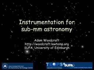
Instrumentation for sub-mm astronomy. Adam Woodcraft http://woodcraft.lowtemp.org SUPA, University of Edinburgh. Introduction. 1. Sub-mm astronomy. Astronomy at sub-mm wavelengths Between infrared and millimetre No strict definition: usually from ~ 200 µm to ~ few mm.

E N D
Instrumentation for sub-mm astronomy Adam Woodcraft http://woodcraft.lowtemp.org SUPA, University of Edinburgh
1 Sub-mm astronomy Astronomy at sub-mm wavelengthsBetween infrared and millimetreNo strict definition: usually from ~ 200 µm to ~ few mm CSO and JCMT,Mauna Kea,Hawaii
Example: sub-mm (850 μm) contours overlaid (SCUBA) Why do sub-mm astronomy? It lets us see cold things - peak in a 10 K blackbody is at 300 μm Cold things are interesting: usually objects in formation (galaxies, stars, planets…) • Sub-mm emission usually “optically thin”; so we see the interior rather than just the surface of objects Example: Eagle Nebula in visible light (Hubble Space Telescope):
Radiation Thermometer Absorber Heat sink Bolometers Dominant detector type for photometry (as opposed to spectroscopy) is the bolometer
2 Semiconductorbolometers
The first bolometer Bolometer invented by S. P. Langley in 1880 for infra-red astronomy (and luminous insects)
Cryogenic bolometers • 81 years later, F. Low developed the cryogenic (4 K) bolometer using doped germanium as the thermistor • Low temperature operation: • Reduces blackbody background radiation • Increases sensitivity: • heat capacity is reduced • doped semiconductors can have very large dR/dT • The original application was not astronomy, but soon adopted (along with the inventor) for IR astronomy
3 Cryogenic bolometers Now replaced by photodetectors in IR, but the detector of choice for photometry in the sub-mm:
Cryogenic bolometers • To get sufficiently good performance, operate at 300 mK or lower • Makes instruments complex (and expensive) • Much lower than needed in most areas of astronomy
Filters Bolometer Cryogenic bolometers • Bolometers are broad-band devices: they respond equally to all absorbed wavelengths • Have to filter out unwanted wavelengths • Metal mesh filters can be produced with precisely defined bandpasses
4 Cryogenic bolometers • For high resolution spectroscopy, astronomers use coherent (heterodyne) systems, as in radio astronomy • Outside the scope of this review • Also operate at low temperatures and challenging to build
Cryogenic bolometers Unlike at optical and infra-red wavelengths, historically few commercial and military applications in sub-mm Development largely in universities and government labs rather than industry Cost $2000/pixel c.f. $0.12 for infrared, $0.01 for optical
Cryogenic bolometers • Composite bolometers introduced in 1970s • Reducing thermal conductance increases sensitivity • But also increases time constant • Reduce again by reducing heat capacity • This is the main reason for such low temperatures • Composite bolometer reduces heat capacity further by separating absorber and thermometer
5 Cryogenic bolometers Early instruments contained a single pixel UKT14 (ROE, Edinburgh)
Bolometer arrays Arrays appeared in the 1980’s, making better use of telescopes SCUBA (ROE, Edinburgh)
SCUBA • Largest of the early arrays • 131 pixels • Composite bolometers (sapphire substrate, brass wire thermal link) • Hand assembled from individual pixels • Arrays (and in particular SCUBA) revolutionised the field
6 NTD germanium • Sensitive and uniform behaviour requires uniform doping • SCUBA and other modern germanium bolometers use Neutron Transmutation Doping (NTD) • Converts 70Ge to 71Ga (acceptor) and 74Ge to 75As (donor) • Since germanium isotopes are uniformly distributed, result is uniform doping and simple behaviour
IRAM- MPIfR 1.3mm array Early instruments JCMT-SCUBA 350/450 & 750/850mm Also 19 pixel 2 mm array at 0.1 K JCMT-UKT14 350mm-2mm CSO-SHARC 350 mm array 91 .3K .3K .1K .1K .3K 37 1 20 37 1986-1996 1998- 1996- 1997- Number of pixels 91 Operating temperature .3K
Modern bolometers • Modern bolometers built by micromachining • Silicon nitride deposited on silicon wafer • Silicon etched to form SiN membranes • Form absorber and supports • Metallisation defines absorber and weak thermal link • “Spiderweb” shape reduces heat capacity and exposure to ionizing radiation JPL spiderweb bolometers
7 Modern bolometers Either break out into individual detectors, or leave to form an array Spiderweb array wafer (JPL) HFI bolometers (JPL/Cardiff) But still have to stick germanium chips individually on each pixel
Modern bolometers • Alternative: make thermistors from the silicon itself by ion implantation • Initial problems with excess noise, but recently discovered it could be removed by using thicker implants SHARC-II (GSFC/Caltech)
Modern bolometers • Difficult to multiplex germanium or silicon bolometers without introducing too much noise • Limits array sizes • “CCD-like” CMOS multiplexed silicon arrays have been produced using very high thermistor resistances to increase signals to partially overcome multiplexer noise PACS arrays (CEA/LETI)
8 Current instruments Facility instruments on telescopes now Doesn’t include dedicated PI instruments or CMB instruments
NTD germanium arrays AzTEC (JPL) 144 pixels LABOCA (MPIfR) 295 pixels
Current instruments Facility instruments on telescopes now Doesn’t include dedicated PI instruments or CMB instruments
9 Silicon arrays SHARC-II (GSFC/Caltech) 384 pixels PACS arrays (CEA/LETI) 2560 pixels
Cooling Warming 0.06 0.04 Resistance increase 0.02 Resistance () 0 95.8 96 96.2 Temperature (mK) Superconducting bolometers • Even without multiplexing, fundamental noise limits reached • Solution: superconductors (transition edge sensor; TES) • Very large dR/dT at transition • But have to keep on transition • Key to use in astronomy was realisation (K. Irwin, 1995) that voltage bias keeps them automatically on transition Joule heating decreases Copper Molybdenum Substrate
10 Superconducting bolometers • Has taken ~ 10 years to find and eliminate excess noise sources to make TES arrays practical • Advantages: • Low fundamental noise limits • Can be constructed on an array scale by thin-film deposition and lithography • Can be multiplexed with minimal noise penalty by superconducting electronics • New generation of instruments using TES arrays now in construction and on telescopes
SCUBA-2 • Eight arrays; 1280 pixels each • Constructed from detector and multiplexer silicon wafer, indium bump bonded together like an infrared array Detector wafer Multiplexer wafer Indium bump bonds
SCUBA-2 Somewhat bigger than predecessors Detector wafer Multiplexer wafer Indium bump bonds
11 Current instruments Facility instruments on telescopes now Doesn’t include dedicated PI instruments or CMB instruments
Facility instruments SCUBA-2 (1280 pixels installed here) MUSTANG (64 pixels)
Other arrays Other arrays already on telescope dedicated to CMB work APEX-SZ 55 x 6 pixels (on telescope) MBAC 1024 pixels (on telescope) And many more to come…
12 BUT • Multiplexer fabrication is complex, especially for large arrays • Increasing array sizes further will be very difficult • Too much power sends detector above transition; no response • Worrying for a space mission where background unknown, and can’t fix problems • Semiconductor bolometers work in high background with reduced sensitivity
KIDs • Alternative technology: Kinetic Inductance Device • Use superconductor below transition • Radiation breaks Cooper pairs • like electron-hole pair creation in semiconductor, but with smaller energy gap • Detect by change in AC inductance • Advantage: can read out many devices with single coax • Simple detector fabrication • No complex multiplexer to make • Still need ultra low temperatures though • Looks very promising Prototype KID camera (Caltech/JPL)
13 STJs • Superconducting tunnel junctions use similar principle • Pair breaking detected by current flowing through tunnel junction which blocks Cooper pairs • Like semiconductor photoconductor • BUT: currently no practical way to multiplex STJ array (ESTEC/ESA)
Other technologies • STJ with RF-SET multiplexer Cold Electron Bolometers + quasiparticle amplifier • SQPT photoconductor QWIPs (quantum wells) Quantum dot devices • Hot-spot superconducting detectors
Antenna coupling • Another area being developed is antenna coupled detectors • Radiation detected by planar antenna • Transmitted to detector by waveguide • Can filter wavelengths electrically rather than optically • One antenna can feed several pixels for different wavelengths
14 X and gamma detection • All these technologies can also be used to detect X and gamma rays • Detect energy pulse from individual photons • Therefore have energy/wavelength resolution • Appealing for X-ray astronomy (and industrial applications) • High resolution and efficiency justify complication of cooling to under 100 mK • Useful since can share development with sub-mm community
Optical/IR • They can even be operated at optical/IR wavelengths • Detect heat from absorption of single photon, and use to determine wavelength! • Unique combination of spatial and spectral measurement along with accurate timing information • Used to measure rapidly varying spectrum e.g. Crab Nebula Optical TES array (Stanford)
15 Conclusions • The next few years will be very interesting: • Many new instruments coming on line • Not clear which technologies will dominate for the next generation of instruments • One current goal is to produce detectors for a space mission with a cold (5 K) mirror • Will have to be considerably more sensitive than current detectors • Different groups developing TES, KID, CMOS multiplexed silicon arrays and many more…
The End 1983 1880 2008