Download
1 / 14
140 likes | 314 Vues
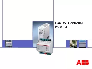
The WSF-700 system is designed to control the fan coil valve and the fan speed of the 5 slave zones with a single master thermostat located in a remote central zone. The master thermostat can check and control the various conditions, and state of the slave zones’ thermostats such

E N D
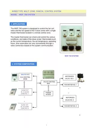
The WSF-700 system is designed to control the fan coil valve and the fan speed of the 5 slave zones with a single master thermostat located in a remote central zone. The master thermostat can check and control the various conditions, and state of the slave zones’ thermostats such as the current temperature, the set temperature, operating hours, time reservation etc very conveniently through a valve control box based on the system communication. WSF-700 SYSTEM MASTER R/T IN A CENTRAL ZONE MOTORIZED VALVE NO.1 VALVE CONTROL BOX FAN MOTOR NO. 1 • • SLAVE R/T IN A SLAVE ZONE NO. 1 POWER AC220V • • MOTORIZED VALVE NO. 5 SLAVE R/T IN A SLAVE ZONE NO.4 FAN MOTOR NO. 5 1
■ A master thermostat can check all working conditions of 4 slave thermostats and control them in a central zone. This system can control max 5 zones. ■ Key Lock function■ AUTO CHANGE OVER function for the heating / cooling control is available. ■ The program for anti-freezing and prevention of overheating is built in.■ 3-fan speed( High, Mid, Low) can be controlled either manually or automatically. 3 – 1 :VALVE CONTROL BOX ■Input Power : AC 220V ± 10% ,50/60Hz ■ Power Consumption : 10W max. ■Output : Valve Actuator : 10W Fan Load : 100W Max. (AC220V) ■ Installation : Wall mounted type ■ Dimension : 185(W) X 140(H) X 50(D) mm 3 – 2 :THERMOSTAT ■ Input Power : DC24(V) ■ Temp range : 5℃~ 35℃ ■Temp setting scale : 0.5 ℃/Step ■Temp Indication Accuracy : 1.0℃ Max ■On-Off differential : 1℃ Max ■ Case Material : Fire resistant ABS plastic ■ Ambient Temp : -20℃~ 50℃ ■ Max Load : Actuator 0.5A Fan motor 3A ■Dimension : Master 80(W)X120(H)X20(D) mm . Slave 92(W)X124(H)X20(D) mm 3 – 3 :ACTUATOR ■ Input Power : AC 220V/50~60 Hz ■ Power Consumption : 3 W ■ Valve Closing / Opening Time : Within 10 seconds ■ Max Operating Pressure : 10 Kg/㎠■ Stroke : 6 mm ■ Max Differential Pressure : 3 Kg/㎠ ■ Ambient Temp : -20℃~ 50℃ ■ Case Material : Fire resistant ABS plastic & Brass ■ Motor : Synchronous and Geared type ■Dimension : 86(W)X65(H)X44(D) 2
☼ ☼ L.C.D Dial SLAVE MASTER SYMBOLS ON A MASTER / A SLAVE THERMOSTAT (1) (2) (3) (4) AUTO MINUTE ℃ ℃ CURRENT TEMP. SETTING TEMP. 1 2 3 4 5 ☼ OUTGO RESERV (6) (12) (11) (10) (8) (7) (9) (5) (1) Room No. (2) Timer (3) Key Lock (4) Fan Speed(5) Current Temperature (6) The Set Temperature (7) Reservation (8) Outgo (9) Heat/Cool state of each zone (10) Operation state of each zone (11) Indication of the heating control (12) Indication of the cooling control 3
DIRECTION FOR USE ( 1 ). POWER : On a valve control box The green power lamp of the control box is ON when the main power switch of a valve control box is “ON”after installation. The present temperature is displayed on a window of the master thermostat and a symbol < - ? - > is blinked on all slave thermostats installedin each zone. : On a master thermostat Press the power button of the master thermostat.A green lamp of the master thermostat is ON. The present temperature (left side) , the previously set point temperature (right side), zone No. 1 and the heating/cooling state are displayed on a window. :On a slave thermostat ① A symbol <- ? -> is displayed on a window once. ② An user shall grant a zone number to each slave thermostat by dialing a knob in each slave zone, otherwise POWER will not be ON. ③ An user can start to manipulate the functions when power is ON. ☞All electric power of the slave thermostats is Off when the power supply of the master thermostat is Off at the closing time in the evening. In the next morning a user has to press the POWER button of the slave thermostat in each zone again so that the slave thermostat can communicate with the master thermostat. ( 2 ). How to set the desired temperature The temperature can be set with master thermostat as below. To change the setting of zone no.2 for example the zone no.2 must be called first. ① When zone no.2 (for example) is displayed on a window of a master thermostat the present and previously set temperatures of zone no.2 are also indicated on either side of the window simultaneously. ② To change the previously set temperature value of this zone no.2 dial a knob of the master thermostat to reach the desired digits to be set as a new temperature value. ③ Then, the new temperature value is displayed on a master thermostat and it blinks 3 times on the salve thermostat of the zone No.2. 4
④ : The new temperature value disappears soon after blinking and instead the present temperature will show up again on a window of the slave thermostat as usual. It means that a slave, a master thermostat and a valve control box have memorized the newly set temperature value and the setting has been completed for all 3 devices finally. (Temperature can be set by 0.5℃unit) NOTE: If a user spends 10 seconds without any setting for the called zone the number of the called zone will disappear on a window of a master thermostat. In this case an user can call the room again by pressing the zone button again. NOTE : An user can check the set temperature whenever he wants by dialing a knob of a slave thermostat a little to the right and left side. NOTE : On a master thermostat the set temperature value of a slave thermostat in each room is always shown so that an user can check it anytime. ( 3 ). TIMER FUNCTION The time setting can be performed on a master thermostat only. This function is to operate the heating/cooling system forcibly for a few minutes within an hour unit regardless the set temperature. ① The TIMER symbol 5 MINUTE is displayed on a window when pressing the TIMER button. ② A user can set the desired heating/cooling time by dialing a knob. The heating/cooling time is indicated by a minute unit. Example : 10 MINUTE The heat/cool system is ON for 10 minutes and Off for 50 minutes. ③ This function is terminated when pressing the TIMER button again. Then, the timer symbol 00 MINUTE is disappeared on a window. ( 4 ). ZONE SELECTION This selection can be performed on a master thermostat only. An user can select a room of which he desires to check and control the state with a master thermostat ① The desired room is selected in sequence No.1~5 when the room button is pressed each time. ② The zone No.1 is a number of the master thermostat’s own. This figure No.1 is indicated first in beginning on a window. ( 5 ). RESERVATION FUNCTION This reservation can be performed on a master thermostat only. An user can reserve the operation time if he wants to operate the heat/cool system at the desired time. ① Press the zone button to call a zone to be reserved.
② Press the fan speed( )and OUTGO buttons( ) over 1.5 seconds at the same time. Then.<The set temperature 00℃> is disappeared on a window. ③ The desired time is indicated first as a figure 12 and a reservation symbol blinks on the window. ④ Dial a knob to the left and right side to reach the desired digits and stop dialing ( Variable hours 1~24). The reservation symbol( )blinks. While this symbol is blinking press the reservation button( ) again. The set temperature and a reservation symbol are displayed on the window. Now, the reservation is completed. ⑤ • The reservation function is terminated when pressing the fan speed • and the outgo buttons at the same time. NOTE : If an user spends 10 seconds without any setting for the called zone the number of the called zone will disappear on a window of the master thermostat. In this case a user can call the zone number by pressing the zone button again. NOTE : To cancel the reservation press the reservation button again. Then “reservation” symbol disappears. It means that the reservation function has been terminated. Example 1 : If an user reserves the operation time as “2” at 10 am and sets the zone temperature at 25 ℃ when going out the system will stay ” un-operated” until 12 o’clock and come into an operation to reach the set temperature 25 ℃ from 12 o’clock. Example 2 : If an user reserves the operation time as “2” at 7 pm and sets the zone temperature for 22 ℃ when going out the system will stay” un-operated” until 9 o’clock pm and come into an operation to reach the set temperature 22 ℃ from 9 o’clock pm. • NOTE : The reservation function can not be performed on the slave • thermostat itself.
( 6 ). OUTGO MODE The heating/cooling system starts to work automatically at this mode when the room temperature becomes below 15℃ under the heating control and above 29℃ under the cooling control. This OUTGO function protects the water distributing pipe from being frozen to burst by operating the heating system automatically when the room temperature becomes below 15℃. ① The set temperature is disappeared and either15℃ in case of the heating or 29℃ in case of the cooling and the OUTGO symbol( ) are displayed at the same time on a window of the master thermostat when the OUTGO button is pressed. The displayed OUTGO symbol means that the OUTGO mode has been set completely. All OUTGO lamps (red) of the slave thermostats are ON because all slave thermostats in the slave zones become under the control of the OUTGO function of the master thermostat at the same time when this setting is done on a master thermostat. This OUTGO button can also be pressed on a slave thermostat of each zone independently for user’s convenience. ② The OUTGO function is terminated when the OUTGO button is pressed again. The set temperature is re-displayed and the OUTGO symbol( )is disappeared on a window when the OUTGO function is terminated. ( 7 ). INDICATION OF HEAT/COOL OPERATION The heat/cooling system starts to work when the difference between the current temperature and the set temperature becomes 1℃. ① The Heat/Cool indicating lamps (Red) on the right upside of a master thermostat and a slave thermostat of the called zone when the Heat/Cooling system comes into the operation. ② And the called zone No. and a symbol( or ) are displayed on a window of a master thermostat. ☼ 1 2 3 4 5 ☼
( 8 ). FAN SPEED It controls the fan speed High, Mid, Low. ① The fan speed is changed in sequence High→ Mid→ Low when the fan speed button is pressed each time. ② The fans speed is changed automatically as per a gap between the set and current temperature (High : Above 4℃ Mid :2~3.5℃ Low :Below 1.5℃) when the fan speed is set as an AUTO mode. ③ The fan keeps on running at a Low speedeven when the valve is closed after the current temperature reaches the se point temperature. ④ The fan speed is changed as being set regardless the temperature gap when the fan speed is set as a manual mode. ( 9 ). KEY LOCK This function can be performed on a master thermostat only. It is designed to lock the operation of a slave thermostat so that no one can manipulate it at his random. ① The key lock symbol is displayed on a window of a master thermostat. ② The symbol is disappeared when the key lock button is pressed again. (10 ). TEMPERATURE COMPENSATION A tolerance of the current temperature can be compensated by this function. ① Cut off the power supply by pressing the power button . Then, the set temperature <0.0> is disappeared on a window. ② Press the FAN SPEED and OUTGO buttons both at the same time over 1.5 seconds. Then, <0.0> is displayed in the position of the set point temperature on a window. ③ Dial a knob to the right and left side to set the compensated temperature. The temperature can be compensated by 0.5℃ within a range -2℃ ~ +2℃. Ex : The current temperature 21.5℃ The compensation -1.0℃ The current temperature is compensated as 20.5℃. ④ An user can exit from this compensation procedure as steps below. Step a : Press theFAN SPEED button . Then it will come to the DELAYED OPERATION. Step b : Press theFAN SPEED button again. Then it will come to the VALVE SELECTION. Step c : Press theFAN SPEED button again. Then it will come to the CHANGEOVER. Step d : Press the FAN SPEED button again. Then it will come out from the TEMPERATURE COMPENSATION finally and the current temperature is displayed as 20.5℃.
(11 ). DELAYED OPERATION It is to delay the operation of the actuators until the set time elapses. To enter in this program on a master thermostat the user has to go through all procedures①②③ of the above Article 10.Temperature Compensation until he arrives at Step a of ④ by pressing the FAN SPEED button one more time after compensation. ② When an user enters into the DELAYED OPERATION mode a figure <05>is displayed on a window. ③ Dial a knob to set the delayed time by 0.5 second unit within a range 0.5~60 seconds. (12) . VALVE SELECTION On a master thermostat an user can set an actuator’s valve type (N.O/N.C) matching with N.O/N.C of the thermostatic valve. To enter in this program on a master thermostat the user has to go through all procedures①②③ of the above Article 10.Temperature Compensation until he arrives at Step b of ④ by pressing the FAN SPEED button one more time after the DELAYED OPERATION. ① When an user enters into a VALVE SELECTION mode two symbols <nOP> and <nCL> are displayed on a window. <nOP>:N.O <nCL>:N.C ② Select one of them by pressing the OUTGO button . (13). CHANGEOVER FOR HEAT/COOL It is to select a cooling system in summer and a heating system in winter. A) Manual changeover : It can be performed on a master thermostat only. ① Remove a jumper <J2>on the Valve Control Box. ② The changeover function is selected by pressing the FAN SPEED button again after the VALVE SELECTION step is finished. ③ Select a heating or a cooling mode when either a heating symbol or a cooling symbol is displayed on a window. ④ Press the FAN SPEED button one more time. Then it will come into the normal operation ☼ B) Auto Changeover - Option ① Insert a jumper < J2 > on the Valve Control Box and connect a pipe sensor with the water distributing pipe. ② The thermostat is changed to the cooling control mode when the temperature of the pipe becomes below 16℃ and the thermostat is changed the heating control mode when the temperature of the pipe becomes above 35℃. ☞ This Auto -Changeover program is performed automatically only by inserting the jumper on the Valve Control Box. (It is not performed on the master thermostat). ☞ The above TEMPERATURE COMPENSATION, DELAYED OPERATION, VALVE SELECTION and CHANGEOVER functions are changed in sequence when the FAN SPEED button is pressed each time.
(14). ERROR SIGNS ① Er 1 : When a sensor of the thermostat is cut off. Er1 indicated on a slave thermostat only. ② Er 2 : When sensor of the thermostat is shorted. Er1 indicated on a slave thermostat only. ③ Er 4 : When a pipe sensor of the Valve Control Box is cut off. Er4 is indicated on all slave thermostats as well as on a master thermostat. ④ Er 5 : When a pipe sensor is shorted. Er5 is indicated on all slave thermostats as well as on a master thermostat (15). HOW TO GIVE A ZONE NUMBER TO EACH ZONE The thermostats come into the normal operation when an user gives a zone number to each zone after installation. It can be performed on each salve thermostat only. ① Select a zone first by dialing a knob when a symbol < -?-> is displayed on a window. The available zone numbers are 2~5.The zone number 1 is for the master thermostat. ② The given number for a zone is set when the RESERVATION button is pressed 3 times after selecting a zone. ③ To reset the zone No. press the RESERVATION and a FAN button at the same time after power-off by pressing the POWER button. Reset the zone number and press the RESERVATION button 3 times. Then zone No. is reset finally. ☞ zone number of each slave thermostat must be same as a number of an actuator to be linked with the Valve Control Box. Otherwise it will not be operated normally. ( 1 ) ( 1 ) Power lamp (Green ) ( 2 ) Heat/Cool indicating lamp ( Red) ( 3 ) Power switch ( On / 0ff ) ( 4 ) 220V power lug ( 5 ) Terminal block for actuators ( 6 ) Terminal block for thermostats ( 3 ) ( 6 ) ( 2 ) ( 5 ) ( 4 ) 8
■POWER ① Put a plug in ( 4 ) after installation and turn on the power switch ( 3 ). Then, the power lamp( 1 ) will be ON. ② The power LED of all thermostats will not be ON unless the power lamp (1) of the valve control box is ON. ■ INDICATION OF SYSTEM OPERATION ①If the indicating lamp ( 2 ) is ON it means that the heating/cooling system starts to work.( This lamp is always ON whenever even a single zone is cooled or heated.) ( 2 ) ( 3 ) Open Closed ( 1 ) • ( 1 )Connecting cable • ( 2 ) Indicating lamp • ( 3 ) Manual open/closing lever • ( 4 ) Valve jointing nut ( 4 ) 1.When the actuator is opened for heating the lamp (2) is ON and the lever(3) is opened. 2.When the actuator is closed the lamp (2) is Off and the lever is also closed. 3.At the time of a power failure use the lever(3) to open or close the valve manually. 9
WIRE SIZE: Above TIV2C*0.8mm Master Slave---Max 4ea WSF-700S WSF-700M VALVE CONTROL BOX: WSF-700C J1 Thermostat J2 J3 Pipe Sensor N H ZONE 1 2 3 4 ZONE 5 ACTUATOR 5 ea FAN :5 ea AC220V,50/60Hz 20A Pipe Sensor (OPTION) Winter / Summer Auto Changeover Only --- Jumper <J2> Insert VCOM V H M L COM White Black Green ACTUATOR EDV-903 FAN Wiring between actuators & fans The heat/cool control is changed automatically when the jumper<J2> is connected and a pipe sensor is installed. (For more details refer to the Article (13) of DIRECTION FOR USE.
Front case Rear cover Junction box ① Separate the rear cover from the front case and mount the rear cover on the junction box and fix it with the enclosed screws.② Pull out the output wires through the fixed hole of rear cover, connect them to the wires of the junction box. ( Refer to the wiring diagram).③ Insert the front case to the locking parts of the rear cover. ① Detach a cover and fix the base to the wall with 2 screws. ② Connect the actuators, the fans, thermostats and a pipe sensor as shown in the above wiring diagram. 10
1. The thermostat should always be mounted in a vertical upright position on an interior wall within the area to be air conditioned and should be located approx 1.5 meters above the floor. This location should be such that thermostat receives adequate air movement to enable it to measure a representative sample conditioned air but it must be away from direct sunlight or draughts from open doors, windows or air conditioning system and never be placed in corners or near cooking appliances etc. 2. When the OUTGO button is pressed the anti-freezing function starts to work. In this case the main valve of the water distributing pipe should be opened. . . ! WARNING : The following instructions must be observed. : The power supply should be cut off when at the time of installation/ un-installation. : The installation/un-installation jobs should be done by an electric engineer with a license. : Keep the inside of a product clean from the foreign matters or water. : User should not disassemble the product at random. : The electric circuit breaker should be installed for safety.