Manfred Meyer & IDT & ODT mmeyer@eso
460 likes | 629 Vues
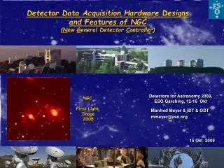
Detector Data Acquisition Hardware Designs and Features of NGC ( N ew G eneral Detector C ontroller). NGC First Light Image 2005. Manfred Meyer & IDT & ODT mmeyer@eso.org. Acquisition System Overview. Acquisition System – Useful Tools. When setting up a detector ….

Manfred Meyer & IDT & ODT mmeyer@eso
E N D
Presentation Transcript
Detector Data Acquisition Hardware Designs and Features of NGC (New General Detector Controller) NGC First Light Image 2005 Manfred Meyer & IDT & ODT mmeyer@eso.org Detectors for Astronomy 2009, ESO Garching, 12-16 Okt
Acquisition System – Useful Tools When setting up a detector …
Monitoring Signals Front Panel Basic Board NGC Two Convert Utility Signal Signal Monitors LED’s Two Clock Monitors Video Monitor Monitor Selection via GUI
Acquisition System – Useful Tools Verifying data flow …
Video Data Simulator (Four Channel System) Simulated Video Data show Counter Values (Counter is incremented on each Conversion Strobe) Simulated video data show channel numbers One Channel One Channel Simulation Mode Selection via GUI
Low Frequency System Noise with H2RG The Hawaii-2RG array has 4 rows and columns of reference pixels around the array Even though good noise performance is achieved (9.55e RMS) when the reference pixel subtraction is activated, this is not the case if the reference subtraction is switched off. Without reference subtraction the noise measured is increased by a factor of two. In this operating mode the detector system suffers from strong low frequency noise and the readout noise is 19e RMS
Measurements on Detector Bias Voltage(Four Video Channels shown) Ceramic Cap TRC = 0.05s • Test with a bias voltage as input to the video chain • Image shows low frequency noise on the bias voltage • ( same input is applied to all four video channels ) One Channel
Detector Bias Cleanup and Resulting Image (All Double Correlated) Tantalum Cap TRC = 1s
Detector Preamplifier (Single Ended Input)
Detector Preamplifier (Differential Input)
Sequencer • Most simple design • But : • Detector readout difficult • to set-up • Not user friendly
Sequencer (realized in FPGA) Contains read-out patterns Contains read-out patterns start addresses and sequence code to be executed EOP = End of pattern RSP = Read speed REP = Number of Repetitions
Sequencer Code Function and Code Interpretation Time (Sequence RAM)
Sequencer Example : PICNIC Array Readout All programming in simple syntax and ASCII code Sequence Pattern (Extract)
NGC Design and Applications
Conventional Approach :Acquisition System (IRACE) PCI Interface Communication and Data Transfer Acquisition Module(s) Sequencer Clock and Bias
NGC System New Design Principle : No Parallel Bus Communication and Data Transfers on High Speed Serial Links with 2 GBit/s
NGC System in Minimum Configuration:Basic Board, Backplane and Transition Board See Demo Set-up in Council Room
NGC System Component : PCI Back-End
Back-End • Function is based on the XILINX Virtex Pro FPGA XC2VP7 FF 672 • Back-End PCI is a 64 Bit PCI board • FPGA contains PCI interface to Communication functions DMA data channel Status and Command • Direct interface from FPGA to PCI without glue logic • PCI master and PCI slave are independent • Scatter – Gather DMA implemented • Communication and data transfers all on serial link with RocketIO transceivers • Handshake communication to Front-End • Data rate on one channel between front and back-end ~ 200MByte/s
NGC System Component : Basic Board
Front-End Basic Board • Function is based on the XILINX Virtex Pro FPGA XC2VP7 FF 672 • FPGA contains link interface for communication and data transfer with RocketIO transceivers, sequencer, system administration, interface to acquisition, clock and bias, telemetry and monitoring • Four ADC channels ( 16 or 18Bit) • 18 clocks, 20 biases • Telemetry • Monitoring • Data rate on one channel between front-end modules and front to back-end ~ 200MByte • Handshake for communication to back-end • Galvanic isolated trigger input and control outputs
Front-End Basic Board Contains everything to read a CMOS sensor or a CCD with up to four video channels 16 or 18 Bit ADC’s Standard 1 MS/s Optional 3 MS/s
NGC System Component : 32 Channel Video Board
AQ 32 Board 32 Video channels 16 or 18 Bit ADC’s Standard 1 MS/s Optional 3 MS/s Double-Correlated Sampling Readout Noise = 6.9 e RMS
Applications with NGC Used as the Building Platform
AO Interface for Tip/Tilt Correction Application : Copy Science Data to SFPDP Link of Real Time Processing System SPARTA Detector Control done with NGC BE
AO Interface for Tip/Tilt Correction All done with standard NGC Back-End Board- only the Firmware was modified
Application : Real Time Processing for Interferometry PMC Based Low Latency DMA Channel DFE is controlled by the PCI Back End Data Transfer from DFE to VME PMC for Interferometry Data also routed through to PCI BE for set-up
Application : Communication Channel to/from ASIC Receiver of Science Data from ASIC all mapped on NGC Fiberlink NGC to ASIC
NGC to ASIC Image of Bare Mux H2RG
NGC High Speed • Eight 40MS/s Pipeline ADC’s • Ten Clocks with Tr/Tf < 5ns • Eight Biases • Telemetry • Clock and Video Monitors • System is modular