Download

1 / 38
450 likes | 1.06k Vues
Vibration Condition Monitoring. Overview of Methods. Maintenance Methods. Method Relative Cost Fix when fail 100% Preventive Maintenance PM 60% Condition Based CM 50% CM + Failure analysis & redesign 30%. CM Methods .

E N D
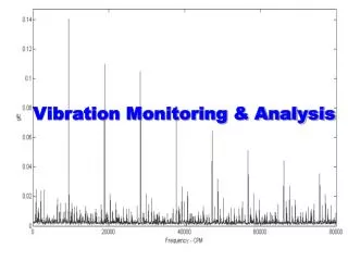
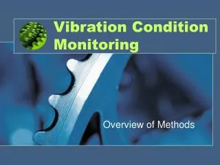
Vibration Condition Monitoring Overview of Methods
Maintenance Methods Method Relative Cost • Fix when fail 100% • Preventive Maintenance PM 60% • Condition Based CM 50% • CM + Failure analysis & redesign 30%
CM Methods Method On load Off load • Visual, Hearing, Touching And Smell X X • Crack Detection X • Leak Detection X • Corrosion X X • Performance Evaluation X • Wear Particle Analysis X • Noise X • Acoustic Emission X • Electric Motor Testing X X • Lubrication X X • Thermal X • Vibration Condition Monitoring (VCM) X
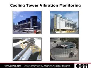
Which machine? • Financial Analysis • Small power tools not cost effective • Major plant permanent monitoring? • Other machines regular screening?
Instrumentation • Transducer • Eddy Current (displacement) • Piezoelectric Accelerometer • Special: SEE, SPM • Conditioning Amplifier • to suit transducer • built in to instrument • Readout/Analyser • Readout, band limited, FFT?
Measurement Location • Measure each vertical position for Trend Analysis • Measure all positions for full analysis, including Tacho / Phase • Convention: number starting at driver 4V 3V 2V 4A 1V 3A 4H 2A 1A 3H 2H 1H Tacho & Phase
Machine Operation • Consistent operating conditions • Loaded, speed • How to detect loading?
OH&S Operator Safety • Location of transducers • Environment while measuring • Safety moving between machines • Emergency procedures • Personal safety equipment
Monitoring • Vertical vibration at each bearing • RMS vibration only • Use trend analysis • Full measurement at each bearing on fault
Trend Analysis Vibration Level V RMS Shutdown level Full Measurement, Analysis & Diagnosis 6 x base level Alarm level Repair 2 x base level Time
Data, Route, Database • Record all data for all points • Regular logical route through plant • Data storage for maintenance intelligence • Data feeds back to monitoring/redesign
Action at Alarm Level • CM measurement exceeds criterion • Fault diagnosis • Maintenance Plan • Spares Requisition
Characteristic Spectrum - Looseness
Resonance • Input vibration that is at or near the natural frequency causes excessive vibration. • About 20% of machines show resonance • May occur with other faults • Can cause excessive energy use • Can cause serious damage
Case Study 1 • Data analysis confirms likely static unbalance • Consider the type of rotor to further examine the fault • Static unbalance is rare - fault means similar loss of mass at each end (eg complete blade from a rotary planer)
Probable Fault • New spectrum bandwidth 5 Hz per line • Large vibration increase at TMF • Gear problem - perhaps excessive wear on one or both gears, failure of tooth hard facing etc. • Check 3H, 3A, 4V, 4H, 4A, 5V, 5H, 5A, 6V, 6H, 6A to confirm.