
An Error Model for Quantum Circuits Using Ion Traps
E N D
Presentation Transcript
An Error Model for Quantum Circuits Using Ion Traps Manoj Rajagopalan
Outline • Motivation • Quantum computing • Linear ion traps • Challenges to implementation • Previous work • Proposed error model • Summary • Future work
Motivation • Practical success of quantum computing hinges on error-correcting codes • Error-correction based on error model • Standard error model makes many assumptions • Practical error models derive from technology • Ion traps among most promising hardware technologies
Motivation • Detailed physical simulation of noisy phenomena computationally infeasible • Logic level error model more tractable • Stuck-at fault model adequate for VLSI testing • Correspondence between logical and physical errors exists for most defects • Quantum systems • Physics-driven simulation: quantum mechanics • Is an adequate logic-level characterization of errors possible?
Quantum Computing • Qubit state • |Ψ = α|0 + β|1, α, β , |α|2 + |β|2 = 1 • |ΨAB = |ΨA |ΨB • Quantum gates • Unitary operators in nn • Reversible evolution • Measurements collapse superpositions to an eigenstate of measurement operator
Quantum Computing • Asymptotic speedup of certain problems • Memory grows exponentially with qubits! • Entanglement: not observed in classical case • Shor’s algorithm • Number factoring, n bits • O(n2 logn loglogn) • Classical (number-field sieve) exp( Θ(n⅓ log⅔n) ) • Grover’s algorithm • Search through unstructured database, size N • Θ(√N) • Classical O(N)
Outline • Motivation • Quantum computing • Linear ion traps • Challenges to implementation • Previous work • Proposed error model • Summary • Future work
Linear Ion Traps • Requirements from quantum hardware • Robust representation of quantum information • Universality of logical transformations • Initial state preparation with high fidelity • Easy high-performance measurements Nielsen and Chuang, Chp. 7
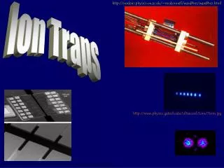
Linear Ion Traps: Apparatus • Four cylindrical electrodes • Two earthed • Two connected to sinusoidal potential • Radial confinement • These also have static potentials at ends • Axial confinement of ions – balance between Coulombic repulsion from electrode and each other. • Radial forces >> axial forces => linear
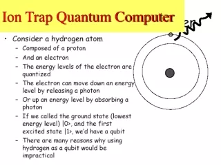
Linear Ion Traps: Logic • Quantum states • Atomic spin (9Be+): internal state • Axial COM motion: motional state • Means of coupling for controlled gates • |Ψ = cos θ |0 + eiφ.sin θ |1 • Quantum gates • Single qubit: zap ion with 1 laser pulse • Duration governs θ, phase governs φ • Controlled NOT [j,k] : 3 laser pulses • Couple spin of ion j with motional mode • Transform spin of ion k if phonon in motional mode • Decouple spin of ion j from motional mode • Universal quantum logic can be implemented
Linear Ion Traps: Logic • Initial state preparation: laser cooling • Doppler cooling: ion-momentum loss to recoil of colliding photon • Sideband cooling: photons absorb energy from lower harmonic of fundamental vibration frequency. • Measurement: light of 313 nm wavelength • |0 flouresces due to special transitions • |1 remains dark
Outline • Motivation • Quantum computing • Linear ion traps • Challenges to implementation • Previous work • Proposed error model • Summary • Future work
Challenges to Implementation • Individual Ion Addressing • Ion separation Q (# ions)-0.56 • Beam focusing • Tightly focused beams – high transverse gradients => high spatial precision required • Focus beam through sharp aperture and image onto ion using lens – good gradients • Destructive interference of counter-propagating Raman beams. • Magnetic field gradients to shift position • RF-field induced micromotion
Challenges to Implementation • Multimode interference • n qubits cause 3n modes of vibration • 1 axial COM mode of interest • 3n-1 spectator modes • Spectator-motion effect on logic gates • Some operations sensitive to frequency that is a function of all modes of motion • Static electric field imperfections • Non-quadratic potentials with jitter causes mode cross-coupling • Net gain/loss of energy →redefinition of frequencies
Challenges to Implementation • Multimodeinterference [contd] • Logic gate induced mode-cross coupling • Spectator modes with frequency-sum or difference ~ transition frequency get coupled to transition states.
Challenges to Implementation • Decoherence • Spontaneous emission • Motional decoherence • Heating from RF fields in trap • Collisions with background atoms • Fluctuating electrode potentials • Thermal noise from lossy elements in electrodes • Electron field emission from electrodes • Coupling of moving charge chain with spurious external EM fields
Challenges to Implementation • Decoherence [contd.] • Noise from applied field • Inaccuracy in targeting ion • Laser pulse timing imprecision • Intensity fluctuations
Outline • Motivation • Quantum computing • Linear ion traps • Challenges to implementation • Previous work • Proposed error model • Summary • Future work
Previous work • Standard error model [Nielsen & Chuang] • Bit flip: X = • Phase flip: Z = • Bit-phase flip: Y = With I, these form basis for space of 22 matrices
Previous Work • Continuum of Operational Errors • Obenland and Despain, Univ. S. California • Single qubit rotations • W(θ,φ) = • Errors: over-rotations or under-rotations • W(θ+Δθ,φ+Δφ) • Error angles Δθ, Δφ chosen as per probability distribution • Fixed magnitude and sign – mis-calibration, bad equipment • Fixed magnitude, random sign – control imprecision • Pseudo-gaussian with given variance – random noise phenomena
Previous Work • Continuum of Operational Errors [contd.] • Controlled-NOT implemented as three 1-qubit rotations (third logic level used as intermediate state) • Each step accumulates errors
Outline • Motivation • Quantum computing • Linear ion traps • Sources of error • Previous work • Proposed error model • Summary • Future work
Proposed Error Model • Over-rotations and under-rotations • Due to inaccuracy and imprecision in controlling various parameters of radiation • Timing • Intensity (jitter, targeting) • Intended Transformation • Resulting transformation
Proposed Error Model • Qubit coupling • Correlated error • Wide laser pulse can illuminate neighbor ion • Intended transformation at target ion • Transformation at affected neighbor • Δθ, Δφfractions of θ and φ respectively. • Like coupling faults in semiconductor memories
Proposed Error Model Stuck-at faults • Stray EM fields in environment • Interaction with background particles • Thermal noise from electrodes • RF heating within trap • Qubit measured in some basis, or • Qubit behaves like a basis state but isn’t in it.
Proposed Error Model • Benignstuck-at faults • Measurement by environment • Not necessarily in computational basis • Logical transformations continue afterwards • Not truly stuck-at: qubit not a physical wire • Resulting transformation • Projective measurement operator • Depends on basis • Depends on state of qubit (normalization)
Proposed Error Model • Catastrophicstuck-at faults • Qubit transition to non-computational-basis state • No further reaction to subsequent pulses • Invariant to further transformations • No flourescence in 313 nm light • Measurement yields |1 (qubit remains dark) • No coupling of internal and motional states • Controlled logic: • If control qubit, behaves as classical |0 ! • If target qubit, invariant to transformation
Outline • Motivation • Quantum computing • Linear ion traps • Sources of error • Previous work • Proposed error model • Summary • Future work
Summary • Ion trap quantum computation explored • Sources of error identified • Operational faults • Decoherence by environment • Previously proposed error model extended • Qubit coupling • Measurement • Depolarization
Future Work • Modeling spectator mode coupling effect • Characterized by an interaction Hamiltonian • Simulations of quantum algorithms • This error model to be used • Comparison with standard error model • Effectiveness of known error-correcting codes • Implications to error-detection and correction