Download
1 / 9
90 likes | 274 Vues
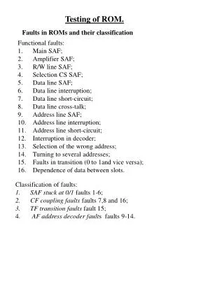
Faults in ROMs and their classification. Testing of ROM. Functional faults: Main SAF; Amplifier SAF; R/W line SAF; Selection CS SAF; Data line SAF; Data line interruption; Data line short-circuit; Data line cross-talk; Address line SAF; Address line interruption;

E N D
Faults in ROMs and their classification Testing of ROM. • Functional faults: • Main SAF; • Amplifier SAF; • R/W line SAF; • Selection CS SAF; • Data line SAF; • Data line interruption; • Data line short-circuit; • Data line cross-talk; • Address line SAF; • Address line interruption; • Address line short-circuit; • Interruption in decoder; • Selection of the wrong address; • Turning to several addresses; • Faults in transition (0 to 1and vice versa); • Dependence of data between slots. • Classification of faults: • SAF stuck at 0/1 faults 1-6; • CF coupling faults faults 7,8 and 16; • TF transition faults fault 15; • AF address decoder faults faults 9-14.
Possible causes of faults in ROMs. • Constant faults: • Connection faults; • Broken components; • Faults in manufacturing; • Faults in design. • Unstable faults: • Environment (temp. humidity, pressure ...); • Vibration; • Feed; • Electromagnetic field, static electricity, ground; • Bad connections; • Timing; • Changes in resistance and capacity, • Noise; • Ageing.
Mask-programmed ROM DC 0 A0 1 2 A 3 3 1 1 b1 b2 Programmable ROM +v +v Fuse 0 DC 1 0 0 A0 1 1 1 1 1 2 0 A 3 1 1 3 b1 0 b2 1
Programming of EPROM The only fuse that falls under the voltage of 2U resulting in its melting . +v +v tension 0 0 tension U1 DC 1 0 0 A0 1 1 tension U1 1 1 1 tension U1 2 0 A 3 1 1 3 b1 b2 tension 2U1 tension 0
EPROM- Erasable PROM Gate Vgg Silicon fixed gate Vss Vdd Source Silicon floating gate Drain p n n EPROM array 0 0 WLi Vdd Vdd Wli+1 Vdd Vdd BLi Bli+1
Functional model of ROM Address Address register Column address decoder Refresh Logic Memory array Line address decoder Transition logic Transition amplifiers Data register Data output Data input Simplified model Address Address decoder Chip Select Memory array Transition logic Data
Behavioral test Functioning ROM Comparison scheme Address generator (Counter) Functioning/ Non- functioning Testified ROM Presupposes the existance of a functioning (golden) object (ROM).
Parity check Functional Testing All words must have even/odd number on 1-s. • 0110 0 • 0001 1 • 1110 1 Parity bits It is not necessary to know how memory has been programmed (content of the memory).
Check sum. Memory ends with the sum of all memory words The number of memory words necessary for preserving the sum depends on the memory capacity Preserving part of the sum (newer/older) some information is lost. It is necessary to know aonly where the check sum is preserved. It is not necessary to know the content of the memory.