Energy Methods
11. Energy Methods. Energy Methods. Strain Energy Strain Energy Density Elastic Strain Energy for Normal Stresses Strain Energy For Shearing Stresses Sample Problem 11.2 Strain Energy for a General State of Stress Impact Loading Example 11.06 Example 11.07 Design for Impact Loads

Energy Methods
E N D
Presentation Transcript
11 Energy Methods
Energy Methods Strain Energy Strain Energy Density Elastic Strain Energy for Normal Stresses Strain Energy For Shearing Stresses Sample Problem 11.2 Strain Energy for a General State of Stress Impact Loading Example 11.06 Example 11.07 Design for Impact Loads Work and Energy Under a Single Load Deflection Under a Single Load Sample Problem 11.4 Work and Energy Under Several Loads Castigliano’s Theorem Deflections by Castigliano’s Theorem Sample Problem 11.5
The elementary work done by the load P as the rod elongates by a small dx iswhich is equal to the area of width dx under the load-deformation diagram. • The total work done by the load for a deformation x1,which results in an increase of strain energy in the rod. • In the case of a linear elastic deformation, Strain Energy • A uniform rod is subjected to a slowly increasing load
To eliminate the effects of size, evaluate the strain- energy per unit volume, Strain Energy Density • The total strain energy density resulting from the deformation is equal to the area under the curve to e1. • As the material is unloaded, the stress returns to zero but there is a permanent deformation. Only the strain energy represented by the triangular area is recovered. • Remainder of the energy spent in deforming the material is dissipated as heat.
If the stress remains within the proportional limit, • The strain energy density resulting from setting s1 = sY is the modulus of resilience. Strain-Energy Density • The strain energy density resulting from setting e1 = eR is the modulus of toughness. • The energy per unit volume required to cause the material to rupture is related to its ductility as well as its ultimate strength.
In an element with a nonuniform stress distribution, • For values of u < uY , i.e., below the proportional limit, • Under axial loading, • For a rod of uniform cross-section, Elastic Strain Energy for Normal Stresses
For a beam subjected to a bending load, • Setting dV = dA dx, • For an end-loaded cantilever beam, Elastic Strain Energy for Normal Stresses
For a material subjected to plane shearing stresses, • For values of txy within the proportional limit, • The total strain energy is found from Strain Energy For Shearing Stresses
For a shaft subjected to a torsional load, • Setting dV = dA dx, • In the case of a uniform shaft, Strain Energy For Shearing Stresses
Sample Problem 11.2 • SOLUTION: • Determine the reactions at A and B from a free-body diagram of the complete beam. • Develop a diagram of the bending moment distribution. • Integrate over the volume of the beam to find the strain energy. • Taking into account only the normal stresses due to bending, determine the strain energy of the beam for the loading shown. • Evaluate the strain energy knowing that the beam is a W10x45, P = 40 kips, L = 12 ft, a = 3 ft, b = 9 ft, and E = 29x106 psi. • Apply the particular given conditions to evaluate the strain energy.
SOLUTION: • Determine the reactions at A and B from a free-body diagram of the complete beam. • Develop a diagram of the bending moment distribution. Sample Problem 11.2
Integrate over the volume of the beam to find the strain energy. Sample Problem 11.2
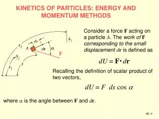
Previously found strain energy due to uniaxial stress and plane shearing stress. For a general state of stress, • With respect to the principal axes for an elastic, isotropic body, • Basis for the maximum distortion energy failure criteria, Strain Energy for a General State of Stress
To determine the maximum stress sm • Assume that the kinetic energy is transferred entirely to the structure, • Maximum value of the strain energy, • For the case of a uniform rod, Impact Loading • Assume that the stress-strain diagram obtained from a static test is also valid under impact loading. • Consider a rod which is hit at its end with a body of mass m moving with a velocity v0. • Rod deforms under impact. Stresses reach a maximum value sm and then disappear.
Example 11.06 • SOLUTION: • Due to the change in diameter, the normal stress distribution is nonuniform. • Find the static load Pm which produces the same strain energy as the impact. • Evaluate the maximum stress resulting from the static load Pm Body of mass m with velocity v0 hits the end of the nonuniform rod BCD. Knowing that the diameter of the portion BC is twice the diameter of portion CD, determine the maximum value of the normal stress in the rod.
Find the static load Pm which produces the same strain energy as the impact. • Evaluate the maximum stress resulting from the static load Pm Example 11.06 • SOLUTION: • Due to the change in diameter, the normal stress distribution is nonuniform.
Example 11.07 • SOLUTION: • The normal stress varies linearly along the length of the beam as across a transverse section. • Find the static load Pm which produces the same strain energy as the impact. • Evaluate the maximum stress resulting from the static load Pm A block of weight W is dropped from a height h onto the free end of the cantilever beam. Determine the maximum value of the stresses in the beam.
Find the static load Pm which produces the same strain energy as the impact.For an end-loaded cantilever beam, • SOLUTION: • The normal stress varies linearly along the length of the beam as across a transverse section. • Evaluate the maximum stress resulting from the static load Pm Example 11.07
For the case of a uniform rod, • For the case of the nonuniform rod, • For the case of the cantilever beam Design for Impact Loads • Maximum stress reduced by: • uniformity of stress • low modulus of elasticity with high yield strength • high volume
Strain energy may also be found from the work of the single load P1, • For an elastic deformation, • Previously, we found the strain energy by integrating the energy density over the volume. For a uniform rod, • Knowing the relationship between force and displacement, Work and Energy Under a Single Load
Transverse load • Bending couple • Torsional couple Work and Energy Under a Single Load • Strain energy may be found from the work of other types of single concentrated loads.
If the strain energy of a structure due to a single concentrated load is known, then the equality between the work of the load and energy may be used to find the deflection. • Strain energy of the structure, From the given geometry, • Equating work and strain energy, From statics, Deflection Under a Single Load
Sample Problem 11.4 • SOLUTION: • Find the reactions at A and B from a free-body diagram of the entire truss. • Apply the method of joints to determine the axial force in each member. • Evaluate the strain energy of the truss due to the load P. Members of the truss shown consist of sections of aluminum pipe with the cross-sectional areas indicated. Using E = 73 GPa, determine the vertical deflection of the point E caused by the load P. • Equate the strain energy to the work of P and solve for the displacement.
SOLUTION: • Find the reactions at A and B from a free-body diagram of the entire truss. • Apply the method of joints to determine the axial force in each member. Sample Problem 11.4
Evaluate the strain energy of the truss due to the load P. • Equate the strain energy to the work by P and solve for the displacement. Sample Problem 11.4
Deflections of an elastic beam subjected to two concentrated loads, • Compute the strain energy in the beam by evaluating the work done by slowly applying P1 followed by P2, • Reversing the application sequence yields Work and Energy Under Several Loads • Strain energy expressions must be equivalent. It follows that a12=a21 (Maxwell’s reciprocal theorem).
Strain energy for any elastic structure subjected to two concentrated loads, • Differentiating with respect to the loads, • Castigliano’s theorem: For an elastic structure subjected to n loads, the deflection xj of the point of application of Pj can be expressed as Castigliano’s Theorem
In the case of a beam, • For a truss, Deflections by Castigliano’s Theorem • Application of Castigliano’s theorem is simplified if the differentiation with respect to the load Pj is performed before the integration or summation to obtain the strain energy U.
Sample Problem 11.5 • SOLUTION: • For application of Castigliano’s theorem, introduce a dummy vertical load Q at C. Find the reactions at A and B due to the dummy load from a free-body diagram of the entire truss. • Apply the method of joints to determine the axial force in each member due to Q. Members of the truss shown consist of sections of aluminum pipe with the cross-sectional areas indicated. Using E = 73 GPa, determine the vertical deflection of the joint C caused by the load P. • Combine with the results of Sample Problem 11.4 to evaluate the derivative with respect to Q of the strain energy of the truss due to the loads P and Q. • Setting Q = 0, evaluate the derivative which is equivalent to the desired displacement at C.
SOLUTION: • Find the reactions at A and B due to a dummy load Q at C from a free-body diagram of the entire truss. • Apply the method of joints to determine the axial force in each member due to Q. Sample Problem 11.5
Combine with the results of Sample Problem 11.4 to evaluate the derivative with respect to Q of the strain energy of the truss due to the loads P and Q. • Setting Q = 0, evaluate the derivative which is equivalent to the desired displacement at C. Sample Problem 11.5