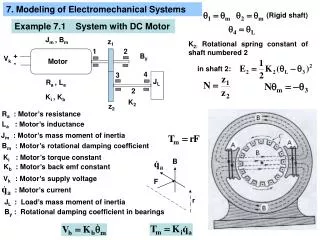
Electromechanical Systems
Asinchronous ( induction ) machines. Types of machines with alternating current Types of induction machines with alternating current Components of asinchronous (induction) machines, (squirel cage and slip-ring induction machines) How does it works! Mathematical model

Electromechanical Systems
E N D
Presentation Transcript
Asinchronous (induction) machines • Types of machines with alternating current • Types of induction machines with alternating current • Components of asinchronous (induction) machines, (squirel cage and slip-ring induction machines) • How does it works! • Mathematical model • Equivalent circuit • Vector (phasor diagram) Electromechanical Systems
Literature • R. Wolf: Osnove električnih strojeva, Školska knjiga, Zagreb, 1991. (72-95, 107-117, dijelovi 181-220), inCroatian • B. Jurković: Elektromotorni pogoni, Školska knjiga, Zagreb, 1985. (Statička stanja elektromotornih pogona s asinkronim motorima, str.49-62), inCroatian • 3. D. Ban: Mirna, pulzirajuća i okretna magnetska polja, predavanja (pogledati dodatnu literaturu na web stranicama), inCroatian
Electrical machines- types Stator with 3 phase winding Stator with winding Rotor, squirel cage or slip-ring type Asynchronous machine Synchronous machine Rotor with permanent magnets Stator with winding on the pole Stator with electromagnet or permanent magnet DC current machine Reluctant machine Rotor with winding, (armature winding) Iron rotor; different reluctance in different axces !
ASINCHRONOUS (INDUCTION) MACHINES • Induction machine (IM) • Stator with three symetrical (balanced) distributed phases , a, b. c ( windings) Stator windings Rotor winding air gap Fig.1.Cross section of IM a), Spatial stator winding distribution, b)
ASINCHRONOUS MACHINES – industrial construction Fig.2. Two types of induction motors – industrial products
ASINCHRONOUS induction machines • Squirel cage Induction machine (motor), IM • - squirrel cage construction, the rotor winding consists of a number of rotor bars, short-cut by rings from both rotor side, see figures below ring ring bars bars ring ring a) b) Fig. 3. Squirrel cage rotor of induction motor, rings and bars a), squirrel cage rotor industrial product b).
ASINCHRONOUS induction machines • Slip-ring asynchronous (induction, IM) machine • stator is identical as squirrel cage induction motor • rotor has clasical winding, not a bars • usualy 3 windings (phases) on the rotor • rotor winding ends connected to the stationary rings, see figure below rings resistors Fig. 4. Stator and rotor connections of a slip-ring a), squirrel cage rotor industrial product b).
Stator Sliced iron, slices electrically isolated from conductors (windings) placed in slots. There are 3 isolated balanced phase (windings), spaced with 120° (for 2-pole machine). 3-phase symmetrical stators winding is supplied by 3-phase symmetrical voltage supply 120° Rotor Sliced iron, slices electrically isolated from rotor conductors (windings), placed in rotor. Rotor winding is usually 3-phase, in “star” connection. The ends of 3-phase winding are short connected altogether from one side in one point. Three others ends of windings are usually connected , to three slip rings, see Fig. 4. Those rings are connected then on stator connection box. For squirrel cage type rotor, conductors are made from cooper (Cu) or aluminium (Al). Air gap It must be as small as possible, taking into account bearings specifications, as well as a mechanical stress. Smaller air gap resulting in small magnetizing current needed for magnetic field. That field is important for effective electromechanical conversion.
Physical concept of IM • Three phase (3f) IM motor supplied from stator side by symmetrical 3f voltage supply, results with SYMMETRICAL ROTATING FIELD. This field rotate with synchronous speed s(1) • Rotational field “is cutting” rotor conductors by relative speed s- (slip, (2), inducing in conductors (windings) voltage E2=s·E20 , (3) • In short connected rotor winding (squirrel cage rotor) induced voltage (3) will generate current,which will together with rotational field produce tangentional force on the rotor, ie. torque. • Developed torque will accelerate rotor, and after reaching desired speed, (steady state), rotor speed will be close to the synchronous speed, (1) slip (%) (2) slip Synchronous speed (1) p→number of pole pairs (see explanation at the end)
Rotor voltage – dependence of slip • When rotor is blocked (s=1, speed=0), rotational field induce in rotor winding voltage E20 , see Fig.5. • When rotor start to move, relative speed is changing, as well as relative speed between rotational (stator) field against rotor, and voltage E2 is changing according (3) • When the relative speed is zero, ie. s=0, there is no voltage in rotor winding, no current, nor force, no torque!! It means that motor cannot work when s=0. Conclusion is that motor can work only when different speed between rotor and rotational speed exist!!! This phenomena define term ASINCHRONOUS MACHINE. (3) Fig.5. Rotor voltage vs rotor speed
Rotor current frequency vs slip • Rotor voltage and current frequencies are depending of relative speed between rotor and rotational (stator) field. i.e. slip. Those variables have frequency determined by relative speed between rotor and rotational (stator) field. Reminder !!!!
Rotor speed– vs. slip The sam units are used for the synchronous speed ns • rotor rotates with synchronous speed s = 0 • rotor blocked , zero speed s=1 • rotor rotates faster than rotational speed s < 0 • rotor rotates opposite than rotational field speed s > 1
Number of pole pairs- Explanation • The term “1 pair poles” defines the region in the stator of machine where three windings (phases) are simetrically spaced inside stator slots. It is said that the angle between axces of the phases are 120geometricly, Fig.1. a) • In the a) this space is 360, in b) it is180 geometricly. • For one supply stator voltage period, rotating field always passing 1 pair poles space!!!. That means, for one cycle T, rotating field will pass in case a) 360, but in case b) only half space, i.e. 180 geometricly • Conclusion 1: rotating field speed in case a) is 2 times larger than in case b) • Conclusion 2. In the machine with p-pole pairs, rotating field will pass in one T cycle 360/p parts of machine stator space. a) 1par polova b) 1par polova c) 2 para polova
Number of pole pairs- Explanation • Physical process with one pole pairs machine doesn’t changed increasing the number of poles. In that case, all analysis can be performed on one pair poles machines. • In this case the term electrical angle (el), is defined and it is identical to the geometric angle (g) for 2-pole machine, p=1. • Generally, for the case of p- pair poles machine, relation between electrical and geometric angle is (4)
INDUCTION MACHINE – HOW DOES IT WORK Initial position of pulsating field is maximal field (maximal current) (maximal sinusoid) the circles are “maximal red”, vector is maximal right oriented. When the field is zero, vector is in the middle of circle (point!), "circles are red”, current in conductors is zero. Next position is maximum fields in another (left) side, vector is maximal and on the left, circles are red (maximal negative current) Fig.6. Animation of PULSATING field
INDUCTION MACHINE – HOW DOES IT WORK Thru each of 3 winding SYMMETRICAL Y spaced in stators slot (namot A,B i C) flow one of the 3f currents, (delayed each other in120°). The picture shows that each of the fields are PULSATING, only the amount is changing in one position. Resulting field is ROTATIONAL field, (BLACK), the sum of pulsating fields of all 3 phases, with maximal amount 50%,greater than maximum of one phase pulsating field. Fig.7. Animation of SYMMETRICAL ROTATIONAL field (black) and PULSATING fields of each phase (red, green, blue)
INDUCTION MACHINE – HOW DOES IT WORK Fig.8. Animation of ROTATIONAL field (black) and PULSATING fields of each of the 3 phase of IM
INDUCTION MACHINE – HOW DOES IT WORK • The principle of work is based on the force (i.e. torque) generation • Torque is result of rotational field and rotor current . Rotor voltage is induced by rotational stator field • Questions:Why rotor cannot reach the speed of rotational field? How rotor could reach the speed of rotational field? Explain! Fig. 9. Rotational field speed (ns), rotor speed (n), and rotor speed relative to rotational field speed (ns -n)
Induction machine – equivalent circuits • One phase equivalent induction machine circuit E1,I1 - induced stator voltage and current U, U1- stator voltage (supply voltage) R1 - stator winding (coil) resistance R2 - rotor winding resistance X1 - stator leakage reactance X2 - rotor leakage reactance E2 - inducied rotor voltage, E20 - induced rotor voltage, (rotor locked, stator connected to suply voltage, U) f1 - stator voltage frequency, f2 - rotor voltage frequency, N1, N2- stator and rotor number of coils
Induction machine – equivalent circuits Fig.10. Equivalent circuit per phase of induction motor with rotor parameters relative to the stator side • Recalculation of rotor’s parameters to the stator side with parameter (k) (5)
Explanation of the main and leakadge path - transformer Main path secondarywinding Primary winding Leackage path Fig.11. Magnetic field generated from primary side and coupled with secondary side and magnetic field generated from secondary side and coupled with primary side are the main (coupled) magnetic field (12or 21). Magnetic field which couple only primary winding is leakage field 1. Magnetic field which couple only secondary winding is leakage field 2 .
Induction machine_ vector-dijagram with k=1 Fig.12. Vector diagram of induction machine
Rotor current and leakage reactance • Rotor current is defined by induced voltage E2 and rotor impedance Z2: (6) • In standstil E2 =E20, see (3) • This formalism can be applied on leakage reactance, X2σ,, so, • X2σ0 is leakage reactance in standstil, n=0. • Leakage reactance is defined for 50Hz (standstill), and influence of the frequency f2 can be involved multiplying by slip s. • For s=0, rotor current is I2(s)=0 (SYNCRONISM !!!)
Electromagnetic torque-dependence of a voltage and frequency • How torque is changing by stator voltage and frequency? • Assumption: Magnetic (rotating) field in the air gap induce in stator winding voltage e1, defined by neglect • For small slip and small current (load) it can be wrote:
Electromagnetic torque - derivation Electromagnetic torque Mem can be expressed as (10) (11)
Torque speed characteristics-derivation • Machine torque dependence of voltage supply can be described using energy balance, (12) • Detailed derivation can be found in course textual material on the web pages • Primary impedance Z1=R1+jXσ1 is neglected in equivalent circuits. • It shoud be emphasized that motor torque in each working point is proportional to the square of the motor voltage (13)
Machine torque characteristics-Kloss equation • Kloss equation describes general torque-speed characteristics of induction machine. • Functionally, Kloss equation involving two working points: arbitrary working point and working point with maximal slip. • In the example below, developed torque at maximal and nominal (rated) torque are used for calculation (14) (15) Which simplification is used in Kloss-equation?
Torque vs speed characterestics of IM (It doesn’t worth for motors less than 1kW)!! Fig.13. Motor torque vs speed induction motor (IM) characteristics • important 3 points: • s= 1, n=0 - standstil torque, Mk • s= sn,n= nn - rated (nominal) torque, Mn • s= smax, n= nmax - maximal torque, Mmax(Mpr)
Electromagnetictorque-dependenceof a voltageandfrequency • Derivation for torque (1) – (4) has been done with assumption that recalculation factor , see (5), is k=1 • From (10)–(13) it can be seen quadratic relation between torque and magnetic field (voltage). • Expression (14), represent simplified Kloss-equation and can be used for slip-ring motors and squirrel-cage motors without skin effect in rotor slots. If the skin effect is present, Kloss equation (14) can be used only in the region of the small slip.
350 600 300 500 250 400 Electromagnetictorque [Nm] 200 Stator current[A] 150 100 50 0 0 200 400 600 800 1000 1200 1400 1600 0 600 800 1000 1200 1400 1600 speed [rpm] 100 x 10 14 Ulazna (električna) snaga Izlazna (mehanička) snaga 90 12 80 70 10 60 8 Efficiency [%] 50 Electrical and mechanical power[kW] 6 40 30 4 20 2 10 0 0 0 200 400 600 800 1000 1200 1400 1600 200 400 600 800 1000 1200 1400 1600 0 speed[rpm] Fig.14. Simulation results given from mathematical model 300 200 100 0 200 400 speed [rpm] speed[rpm]
Induction machine– energy balance Fig.15. Energy balance in induction motor P1 is electrical power (power supply) P2 is power on the motor shaft (mechanical Power)!!!
Nominal data- Total, Active and Reactive power of IM Example of motor Data: 3f induction motor, P= 1000 kW Voltage 6000 V, frequency 50 Hz nominal speed1485 ,(rpm), cosφ=0,88, =0.8 nominal current 115 A • For magnetic field getting, IM taking reactive power • Total power of IM is • Active power (on the motor shaft!) P=P2 . • m1 is the number of phases
Induction motors - Slip and Losses • The amount of slip is directly indicator of the amount of losses in induction motors (see energy balance). • It is needed to set working point in the way that slip must be very low. • Nominal slip is usually between 0.1 i 5 %. Low power machine (up to cca 1kW), has larger slip. Takeintoaccountthe problem ofoverheating.Highlossesmeanshighheating, conductor’s isolationgettingbadly, it is possibledielectricbreakdown!
Working range of induction squirel cage motor Magnetic field rotation Rotor rotation Generator braking Pluging Motoring Fig.16. 4-quadrant operation s = 0 n = ns unloaded machine s = 0.01 n = 0.99 ns working region of large machines (over 100kW) s = 0.04 n = 0.96 ns working region of medium and small machines s = 1 n = 0 blocked rotor s > 1 revers current braking, pluging s < 0generatory braking