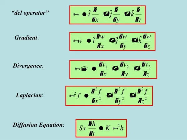
Dual Gradient Drilling Basic Technology
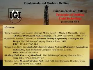
Dual Gradient Drilling Basic Technology. Lesson 1 Introduction to DGD Jerome J. Schubert. Introduction. Current deepwater drilling problems. Introduction, con’t. Brief history of DGD Phase I Phase II Phase III. Introduction, con’t. Describe the DGD System

Dual Gradient Drilling Basic Technology
E N D
Presentation Transcript
Dual Gradient DrillingBasic Technology Lesson 1 Introduction to DGD Jerome J. Schubert
Introduction • Current deepwater drilling problems
Introduction, con’t • Brief history of DGD • Phase I • Phase II • Phase III
Introduction, con’t • Describe the DGD System • How can DGD can solve the existing drilling problems? • Equipment overview
Current Deepwater Drilling Problems • Deeper water results in longer and heavier drilling risers • High pore pressures and low fracture gradients leads to more casing strings
Land Well 2 strings of casing after 20”
500’ Water Depth 2 strings of casing after 20”
1000’ Water Depth 2 strings of casing after 20”
5000’ Water Depth 3 strings of casing after 20”
10,000’ Water Depth 4 strings of casing after 20” with no kick or trip margins
0.5 ppg Standoff 6 strings of casing after 20”
Too many shallow casing points May not reach TD No contingency casing available This leads to larger wellheads, even larger and heavier risers, and finally to bigger and more expensive rigs Current Deepwater Drilling Problems
Well Control is more difficult - because of the pore pressure/fracture proximity, and long choke lines with high friction pressure drops Current Deepwater Drilling Problems
Kick w/ 750 psi SIP Mud HSP (13.1 ppg) Mud HSP + 750 psi Formation has fractured Pore Pressure Fracture Pressure
Very high riser loads (current and weight) Weight of the drilling riser increases with depth. Current Deepwater Drilling Problems
Current Deepwater Drilling Problems • In 10,000’ of water • 21-inch riser has an internal capacity of ~4000 bbls! (~$1 million) • Weight of the riser itself is ~ 2million lbs • Weight of 16 ppg mud inside the riser ~ 2.7 million lbs
Water depths beyond rig fleet New builds and major upgrades Current Deepwater Drilling Problems
Small wellbore at TD precludes large production tubing - limiting production rates Began 2nd quarter of 2000 Current Deepwater Drilling Problems
Drilling’s Major Benefits of DGD • Reduces drilling cost by $5-15 MM per well in young depositional basins (4 casing strings) • Provides contingency casing for SWF’s, sub-salt
Drilling’s Major Benefits of DGD • Allows room for high rate completions • Expands capacity of existing rig fleet • Mitigates effects of high currents • Improves Well Control margin
Describe the DGD System • “DGD” Drilling, in the present context, refers to drilling where mud returns DO NOT go through a conventional, large-diameter, drilling riser. • Instead the returns move from the seafloor to the surface through one or more small - diameter pipe(s) separate from the drillpipe. • A Mudlift system is used in the Return Line • A Dual Gradient mud system is achieved.
Seawater HSP 12.4 ppg mud 13.5 ppg mud Single vs. Dual Gradient Concept • Single Gradient Wells • Wellbore contains a single density fluid • Single pressure gradient • Dual Gradient Well • Wellbore feels seawater gradient to the seafloor, and mud gradient to bottom Pressure, psi Depth ft Seafloor @ 10,000’ 23,880 psi @ 37,500’
Dual Gradient Achieved by: • Placing SRD on top of the BOP stack and diverting the mud flow from the annulus to the MLP • The MLP then pumps mud back to the rig via the return lines • Suction pressure to the MLP is maintained at Seawater HSP + ~20 to 50 psi
Single vs. Dual-Gradient Mud Systems Dual Gradient Conventional Heavier Mud w/ Seawater Above Mudline Single Mud Weight Same Bottom Hole Pressure From the perspective of the well, there is no mud above the mudline in a dual-gradient system! Figure 3
How can DGD can solve the existing drilling problems? • By placing the MLP on the seafloor we can reduce the pressure exerted on the shallow weak formations and still maintain the required pressure at the bottom of the hole to control formation pressure • Riser margin is back - emergency disconnect and drive-off will not result in an automatic kick.
Dynamic Casing Seat Selection Pressure, psi D e p t h ft. 1.0 ppg kick 0 bbl influx volume Frac. Press. Pore Press.
Dynamic Casing Seat Selection Frac. Press. 1.0 ppg kick 50 bbl influx volume Pore Press.
Kick Tolerance is Back Conventional DGD 20” @ 12,500’ 16” @ 13,000’ 13 3/8” @ 14,000’ 11 3/4” @ 15,000’ 9 5/8” @ 17,500’ 7 5/8” @20,000’ 5 1/2 “ @ TD 0.5 ppg standoff no influx 20” @ 12,500’ 16” @ 14,000’ 1.0 ppg kick, 50 bbl influx 13 3/8” @ 17,000’ 11 3/4” @ 22,800’ 9 5/8” @ TD
Equipment overview • Marine Riser • SRD - SubSea Rotating Diverter • DSV - Drillstring Valve • MLP - MudLift Pump • Return Lines • Manifolding • Dual Trip Tanks
Seawater Pumps (Existing Mud Pumps) Seawater Power Line, Control Umbilicals SubSea MudLift Configuration Mud Returnand Pump Return Line Drillpipe Seawater Filled Marine Riser Rotating Diverter Seawater-Driven MudLift Pump Wellhead and BOP BHA Drill String Valve
Marine Riser • Essentially a conventional riser filled with seawater
Wellbore Components Return Outlets Riser Adapter Subsea Rotating Diverter (SRD)
Drill String Valve (DSV) Flow Nozzle Closing Spring
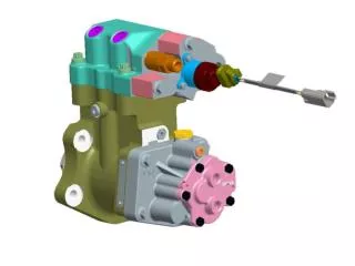
Mud Enters the Diaphragm Pumps Displacing the Mud Back to the Rig Seawater Pumped from the Rig While Seawater Discharged to Sea Mud Inlet Mud Outlet Seawater Driven MudLift Pump
Diaphragm Pump Stroke Indicator Sensor (Fixed) Stroke Indicator Magnet Assembly Hydraulic Fluid In/Out Stroke Indicator Tube (Moving) Connection to Diaphragm Diaphragm Mud In/Out
Seawater Driven MudLift System 14’ x 17’ x 11’h 175,000 lbs plus Seawater Conduit ROV-Style Cables Mud B C K H Seawater
The End Jerome J. Schubert Introduction to DGD