Download
1 / 30
310 likes | 507 Vues
Chapter 17: Electric Forces and Fields. Objectives. Understand the basic properties of electric charge. Differentiate between conductors and insulators. Distinguish between charging by contact, charging by induction, and charging by polarization. Electric Charge.

E N D
Chapter 17: Electric Forces and Fields
Objectives • Understand the basic properties of electric charge. • Differentiate between conductors and insulators. • Distinguish between charging by contact, charging by induction, and charging by polarization.
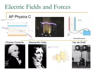
Electric Charge • Ben Franklin: two kinds of charge, positiveand negative • opposite charges attract; like charges repel • Law of Conservation of Charge:it can’t be destroyed, total is constant • charge (q) is measured in coulombs (C) • electrons (–), protons (+) • Robert Millikan (1909): fundamental charge = +/– 1.60 x 10⁻¹⁹ C
Transfer of Electric Charge • charges move freely through conductors (typically metals, ionic solutions) • charges do not move freely in insulators (most other substances) Electric charge can be transferred 3 ways: • friction/contact • induction • polarization
Objectives • Calculate electric force using Coulomb’s law. • Compare electric force with gravitational force.
Coulomb’s Law Law of Universal Gravitation Coulomb’s Law k = 8.99 x 10⁹ Nm2/C2
Which is Stronger, Fe or FG? • Compare the Fg and the Fe between the p+ and e- in a hydrogen atom (r = 53 pm).
Objectives • Calculate electric field strength. • Draw and interpret electric field lines. • Identify the properties associated with a conductor in electrostatic equilibrium.
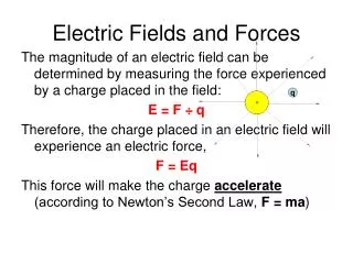
Electric Fields • Field lines show direction and strength of force (represented by the line density) acting on a charge • E-field: (+) → (–) • units are N/C
Electric Fields The nucleus applies a force of 8.16 x 10⁻¹¹N on the electron in a hydrogen atom. What is the electric field strength at the position of the electron? What is the orbital period of the electron, assuming it orbits in a circular path (it really doesn’t)?
Conductors in Electrostatic Equilibrium electrostatic equilibrium: no net motion of charge (a) The total electric field inside a conductor equals zero. (b) Excess charge resides on the surface. (c) E-field lines extend perpendicular to the surface. (d) Charge accumulates at points.
Objectives • Understand the concept of electric potential energy (EPE). • Calculate the DEPE when a charged particle is moved in a uniform electric field.
Electric Potential Energy (EPE) • uniform field only! • displacement in direction of the field g E
EPE Problems • What is the change in EPE if a proton is moved 2.5mm in the direction of a uniform 7.0 x10¹¹ N/C electric field? • What is the change in EPE if an electron is moved in the same direction?
Potential Difference (Voltage) • voltage (V) is EPE per charge • 1 volt = 1 J/C • measured with a voltmeter • voltage is like an “electric pressure” that pushes charges • batteries, outlets, generators, etc. supply voltage (uniform field only)
Voltage Problems What voltage exists in a 3.5 x10⁻⁶ N/C electric field between two points that are 0.25 m apart?
Capacitors • Capacitors store EPE between two closely-spaced conductors (separated by an insulator). • Capacitance is measured in farads (F). 1 F = 1 C/V • Capacitors can discharge very quickly—producing short bursts of electrical current
Chapter 19: Electric Current and Electric Power
Electric Current Electric charges will flow between areas of different electric potential (voltage) • electric current (I): a flow of • electric charge • 1 ampere (A) = 1 C/s • measured with an ammeter • although electrons typically flow, current is • defined as direction of positive flow (+ → –) • drift speed of e– in Cu at 10 A is only 0.00025 m/s • 0.005 A is painful and 0.070 A can kill you
Electric Resistance • resistance (R): resistance • to electron flow • measured in Ohms (Ω) • V ↑, I↑ • R ↑, I ↓ A 2400-Ω resistor is attached to a 12-V power source. What is the current through the wire?
AC/DC • alternating current: electric field reverses periodically, current alternates direction(60 hz in USA) • direct current: field is constant, current is constant • batteries produce DC • electric generators can make AC or DC
Electric Power and Energy Consider the units of voltage: Electric power is transported at high voltage and low current to minimize “I2R loss.”
Power Problems An electric oven operates on a 240 V circuit (not the regular 120 V). How much current flows through the element in the oven if the power usage is 3200 W? At $0.06 / kW·hr, how much does it cost to operate a 280-W television for 2 hrs?
Objectives • To understand the concepts of series and parallel circuits. • To calculate the total resistance and current flowing through a circuit containing series and/or parallel circuits.
Series Circuit • Resistors (or loads) “in series” just combine to make a larger resistance. • RT = R1 + R2 + R3 + … • In a series circuit, if V = 12 V, R1= 1 Ω, R2 = 2 Ω, and R3= 3Ω, what is RT and current? • What is the “voltage drop” across each resistor? • Holiday lights are often in series: if one bulb burns out, nothing works!
Parallel Circuits • Resistors in parallel provide additional paths for current to flow, so resistance decreases. • 1/RT= 1/R1+ 1/R2+ 1/R3+ … • In a parallel circuit, if V = 12 V, R1 = 1 Ω, R2 = 2 Ω, and R3 = 3 Ω, what is RTand IT flowing through the entire circuit? What is the current in each resistor? What is the voltage drop across each resistor? • Household circuits are wired in parallel.
Voltage Drops • The current flowing through a resistor depends on the voltage drop “across” the resistor. • Series example: V = 12 V, R1 = 1 Ω, R2 = 2 Ω, and R3 = 3Ω • Parallel example: V = 12 V, R1 = 1 Ω, R2 = 2 Ω, and R3 = 3 Ω