On Clock Network Design for Sub-threshold Circuitry
220 likes | 374 Vues
On Clock Network Design for Sub-threshold Circuitry. Yanqing Zhang University of Virginia yz4hz@virginia.edu. Outline. Introduction and Motivation Problem Analysis Slew Aware Clock Design for Sub-threshold A Clock Buffer Design for Sub-threshold

On Clock Network Design for Sub-threshold Circuitry
E N D
Presentation Transcript
On Clock Network Design for Sub-threshold Circuitry Yanqing Zhang University of Virginia yz4hz@virginia.edu
Outline • Introduction and Motivation • Problem Analysis • Slew Aware Clock Design for Sub-threshold • A Clock Buffer Design for Sub-threshold • Clock Topology Discussion for Sub-threshold • Summary • Questions
Outline • Introduction and Motivation • Problem Analysis • Slew Aware Clock Design for Sub-threshold • A Clock Buffer Design for Sub-threshold • Clock Topology Discussion for Sub-threshold • Summary • Questions
Intro: Sub-threshold Operation • Voltage scaling leads to quadratic savings in Pdyn • Pdyn=α0-1CeffVDD2f • Scaling is pushed into sub-threshold(sub-VT) region • Transistor devices not “on”… • …but still operational • Sacrificing performance(speed) for low power/energy • Sub-VT characterized by weak drive and long delay • And great savings in dynamic power/energy • Wide application space • Mobile electronics • Environmental/body sensor nodes Sub-VT
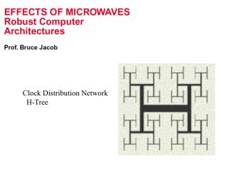
Intro: Clock Networks for Digital Circuits • Conventionally, H-trees provide: • Optimal slew(10%-90% VDD transition time in clock signal) • Optimal skew(phase difference between clock signal at difference registers) • Slew and skew affect timing constraints CAUSES TIMING VIOLATIONS logic REG D Q REG D Q CLK tslew CLK CLK’ CLK CLK’ δ CLK’ Ideal Clock Example H-tree Practical Clock Example
Intro: Clock Networks for Digital Circuits HDL Coding module example(…) … endmodule • Timing yield dependant on clock network • Setup constraint • Hold constraint • tc-q, tsu, tholdwith tslew • Clocks designed via clock synthesis • Designer has control over tslew,max, Cmax, δmax Logic Synthesis Well defined. Final Route Clock Synthesis[ref] Placement =
Outline • Introduction and Motivation • Problem Analysis • Slew Aware Clock Design for Sub-threshold • A Clock Buffer Design for Sub-threshold • Clock Topology Discussion for Sub-threshold • Summary • Questions
Sub-threshold Problems for Clock Network • Setbacks of sub-threshold impose difficulty for quality clock network • Exponential dependency on VT variation vs • Low drive strengths (~103× less) • Wire delay no longer a factor • Wire load still relevant • Direct Impact on Clock Network • Both skew and slew • Slew also increases short circuit power Transistor Vgs-ID curve[1] Delay(s) Monte Carlo simulation of delay exhibiting non-Gaussian distribution Skew degradation with process variation[3]
Sub-threshold Problems for Clock Network • Slew a problem in sub-threshold • Short circuit power(not a focus in super-threshold) • Low drive strength=less control(10’s ns vs. 1 ps) • Scaling won’t work • Up to 90% deterministic variation in timing parameters • Can re-design directly in sub-threshold, but undermines low power Example of register Scaled Clock Tree [2] [2]
Outline • Introduction and Motivation • Problem Analysis • Slew Aware Clock Design for Sub-threshold • A Clock Buffer Design for Sub-threshold • Clock Topology Discussion for Sub-threshold • Summary • Questions
Slew Aware Clock Tree Design for Sub-threshold • Tighter nodal capacitance constraint CMAX will corral slew • Slew recovery through buffer is stronger function of CMAX than input slew • Therefore, use higher CMAX near clock source, smaller CMAX at registers Relationship between slew, CMAX , and power [2] Output slew vs. load cap and input slew [2] Resulting clock tree shape [2] [2] Resulting optimization
Outline • Introduction and Motivation • Problem Analysis • Slew Aware Clock Design for Sub-threshold • A Clock Buffer Design for Sub-threshold • Clock Topology Discussion for Sub-threshold • Summary • Questions
A Clock Buffer Design for Sub-threshold • Problem arises from operating in sub-threshold • Solution: circuit in sub-threshold, clock network not • Capacitive Boosting: • Boosts ‘overdrive’ to higher than VDD • No level converter overhead Concept of capacitive boosting[4]
A Clock Buffer Design for Sub-threshold • Shortcomings: • Higher static and leakage power/energy for buffer • Greater area • Not integrated into design flow • Complexities with timing and clock gating(1/2 cycle startup) • Doesn’t save power at lower frequencies for set VDD • Doesn’t necessarily address process variations • Advantages: • Drastic improvement in slew (2.6x at 0.4V, 1 pF load) • Better overall clock network energy due to fewer # of buffers • Drastic improvement in skew Improvement in slew[4] Improvement in skew[4] Overall improvement in energy consumption for clock network[4]
Outline • Introduction and Motivation • Problem Analysis • Slew Aware Clock Design for Sub-threshold • A Clock Buffer Design for Sub-threshold • Clock Topology Discussion for Sub-threshold • Summary • Questions
Clock Network Design for Sub-threshold • Conventional tree scrutinized • Buffers perform poorly, do we really need them? • Buffers NOT optimal in face of process variations • Case study to compare buffered vs. non-buffered trees vs Buffered vs. non-buffered trees to be compared[3] Energy overhead incurred under same nominal skew constraint for non-buffered trees[3] Skew and slew improvement with non-buffered trees[3]
Clock Network Design for Sub-threshold • Measurements show improvement in skew, skew variation, and slew variation without much overhead • 4 orders of magnitude less skew • 28% less slew variation • 4% power overhead • Drawback: design not suitable across all VDDs • Drawback: design not suitable across all circuit sizes • Drawback: design not suitable across all constraints Skew and slew improvement with non-buffered trees[3]
Outline • Introduction and Motivation • Problem Analysis • Slew Aware Clock Design for Sub-threshold • A Clock Buffer Design for Sub-threshold • Clock Topology Discussion for Sub-threshold • Summary • Questions
Summary • No universal solution • Scope and limitations to individual methods • Slew Aware Clock Tree Design for Sub-threshold: • Good for slew control by design • Universal for all clock network topologies • Always saves something in power • Does not address variations • Should be used as an auxiliary method • A Clock Buffer Design for Sub-threshold: • Fantastic performance with regards to slew and skew • Given range of supply voltage that it addresses process variations • Ridiculous increase in power/energy for single buffer • Thus restricted to certain frequencies and design sizes • Clock Network Design for Sub-threshold • Method address slew, skew, process variations • Power/energy overhead fluctuates with design characteristics • What does it all mean? • Imminently, no universal solution • We should carefully observe the characteristics of our design, and design accordingly • Example: Combine papers [3] and [4]?
References [1] B. H. Calhoun., A. Wang, N. Verma, A. P. Chandrakasan, "Sub-threshold Design: The Challenges of Minimizing Circuit Energy," International Symposium on Low Power Electronics and Design (ISLPED), pp. 366-368, October 2006. [2] J. R. Tolbert, X. Zhao, S. K. Lim, S. Mukhopadhyay, “ Slew-Aware Clock Tree Design for Reliable Subthreshold Circuits”, ISLPED, August 2009. [3] JonggabKil, et al, “A High-Speed Variation-Tolerant Interconnect Technique for Sub-threshold Circuits Using Capacitive Boosting,” ISLPED, 2006, pp. 67-72. [4] MingooSeok, D. Blaauw, D. Sylvester, "Clock Network Design for Ultra-Low Power Applications,"International Symposium on Low Power Electronics and Design, Aug, 2010.