5.9 WAVE / DSRC CONCEPT
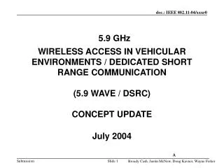
5.9 GHz WIRELESS ACCESS IN VEHICULAR ENVIRONMENTS / DEDICATED SHORT RANGE COMMUNICATION (5.9 WAVE / DSRC) CONCEPT UPDATE July 2004. A. 5.9 WAVE / DSRC CONCEPT.

5.9 WAVE / DSRC CONCEPT
E N D
Presentation Transcript
5.9 GHz WIRELESS ACCESS IN VEHICULAR ENVIRONMENTS / DEDICATED SHORT RANGE COMMUNICATION (5.9 WAVE / DSRC)CONCEPT UPDATE July 2004 A
5.9 WAVE / DSRC CONCEPT 5.9 GHz WAVE / DSRC (Dedicated Short Range Communications) is a short to medium range communications service that supports both Public Safety and Private operations in roadside-to-vehicle and vehicle-to-vehicle communication environments. 5.9 WAVE / DSRC is meant to be a complement to cellular communications by providing very high data transfer rates in circumstances where minimizing latency in the communication link and isolating relatively small communication zones are important. A
5.9 GHz DSRC BAND PLAN Shared Public Safety/Private Dedicated Public Safety Med Rng Service High Avail Intersections Short Rng Service Control Power Limit 44.8 dBm 40 dBm Power Limit 33 dBm Power Limit 23 dBm Uplink Downlink Public Safety Public Safety/ Private Public Safety/ Private Public Safety/ Private Public Safety/ Private Public Safety Intersections ControlChannel Ch 180 Ch 182 Ch 172 Ch 184 Ch 178 Ch 174 Ch 176 5.875 5.880 5.905 5.910 5.850 5.855 5.860 5.865 5.870 5.885 5.890 5.895 5.900 5.920 5.925 5.825 5.845 5.835 5.830 5.915 5.840 Canadian Special License Zones* Frequency (GHz)
5.9 WAVE / DSRC USAGE REQUIREMENTS • INTEROPERABILITY of UNITS from DIFFERENT MANUFACTURES • PUBLIC SAFETY and PRIVATE APPLICATIONS SHARE UTILIZATION of the 5.9 GHz BAND • PUBLIC SAFETY MESSAGES HAVE PRIORITY • 100 ms or less ACCESS TIME to Safety Messages • CONTROL CHANNEL MUST NOT FAIL UNDER CONGESTED CONDITIONS • HIGH TRANSFER RATE EFFICIENCY DURING HIGH SPEED MOBILE DATA TRANSACTIONS
5.9 WAVE / DSRC USAGE REQUIREMENTS (continued) • WAVE-SPECIFIC APPLICATION SUPPORT • NON-WAVE SPECIFIC APPLICATION SUPPORT • GENERAL PURPOSE INTERNET (GPI) APPLICATION SUPPORT • PRIVATE and SECURE OPERATION • RSUs CONTROL LICENSED CHANNELS IN THE DESIGNATED COMMUNICATIONS ZONE • OBUs TRANSFER SAFETY DATA ON WIDE AREA CHANNELS WITH ONLY THE CSMA MECHANISM RESTRICTION
5.9 WAVE / DSRC USAGE REQUIREMENTS (continued) • Receipt of Vehicle Safety Messages must not be interrupted for extended periods of time. Extended periods of time probably means somewhere between 100 and 500 ms or more • Some transactions will take more than 100 ms to complete and we want to maximize the efficiency of channel usage • The Car companies want the ability to implement Vehicle Safety Messages and the Cooperative Collision Avoidance Application with a one channel radio
PUBLIC SAFETY Messages Have Priority • Management Frames have a higher priority than any priority of data frame. Beacon Frames have the highest priority but only one level. Levels of Priority must be added to Action Frames. • High Priority Public Safety Broadcast Messages are sent in Wave Service Information elements in Beacon Frames from RSUs or Action Management Frames from OBUs. • Quality of Service Data Frames have priority levels that allow further delineation of priority among applications • Private Application Messages are sent in Action Frames on the Control Channel and Quality of Service Data Frames in Service Channels
Updated WAVE Architecture IVN OBU App 3 SNMP agent (RFC 1157) App 2 App 1 UDP (RFC 768) SME (802.11) WME (802.11p/1609.3) UDP SNMP MIB Networking Services (IPv6 – RFC 2460) Networking Services Logical Link Control (802.2) IVN L2/L1 IVN L2/L1 Channelizer (1609.4) Channelization (1609.4) MLME(802.11p) MAC (802.11p/ ASTM E2213) • Notes: • Each device may have a single SNMP manager servicing multiple applications. • Role of 1609.1 & 1609.2 needs furtherdiscussion. For now, the applications areshown in a general context to focus onthe lower layers. PLME(802.11p) PHY (802.11p/ ASTM E2213)
Possible 5.9 WAVE Control and Service Channel Implementation Options • Short Public Safety Messages may be included as elements in Beacon and Action Frames to be Broadcast on the Control Channel • High Priority messages may be Broadcast on all the service channels • Extended Public Safety Message exchanges may occur with Unicast data frames on Service channels • Private Application Messages may be Broadcast in Action Frames on the Control Channel with strict interval and size limits (as listed on a following slide) • Private Application Messages may be Broadcast or Unicast on a selected service channel • Private Application Message exchanges occur with unicast data frames on Service channels
Control Channel Rules Shared Public Safety/Private Dedicated Public Safety Med Rng Service High Avail Intersections Short Rng Service Control • 1. Broadcast • Beacon Frame (RSUs only) • Action Frame (Safety - NO limits) • - Action Frame (Private Messages - subject to limits shown on the following slide) • 2. Unicast (RSU only ) • - Action Frame (Safety - NO limits) • - Action Frame (Private subject to limits) 5.875 5.880 5.905 5.910 5.850 5.855 5.860 5.865 5.870 5.885 5.890 5.895 5.900 5.920 5.925 5.825 5.845 5.835 5.830 5.915 5.840 Frequency (GHz)
Service Channel Rules Shared Public Safety/Private Dedicated Public Safety Med Rng Service High Avail Intersections Short Rng Service Control • 1. Broadcast • - Beacon Frame (RSUs only) • - Action Frame (Safety NO limits) • - Data Frame • - All other frames • Unicast • - Data Frame • - All Other Frames 5.875 5.880 5.905 5.910 5.850 5.855 5.860 5.865 5.870 5.885 5.890 5.895 5.900 5.920 5.925 5.825 5.845 5.835 5.830 5.915 5.840 Frequency (GHz)
ACTION FRAME CONTROL CHANNEL USAGE LIMITS Below is a table that defines the limits of Control Channel usage for private applications using broadcast or unicast action frame transmissions. 1. For Private Applications: RSUs OBUs Maximum Data Transmission Duration: 750 usec 580 usec Minimum Interval between Data Transmissions: 100 msec* 750 msec *20 msec Minimum Transmissions Intervals are allowed in low power (20 dBm EIRP) operations. 2. Applications are not allowed to respond on the Control Channel to announcements of RSU or OBU Application Services.
DEFINITIONS WAVE Beacon: • A WAVE beacon is composed of a WAVE Service Information Element added to the IEEE 802.11 beacon. • The WAVE Service Information Element is composed of a Provider Service Table (PST), a WAVE Routing Advertisement (optional), a Safety Message (optional), and Authentication elements.
DEFINITIONS WAVE Action Frame: • A WAVE action frame contains the WAVE Service Information Element • The WAVE Service Information Element is composed of a Provider Service Table (PST), a WAVE Routing Advertisement (optional), a Safety Message (optional), and Authentication elements.
DEFINITIONS Provider Service Table: • A set of data that identifies applications being offered • Identification of the hosting device • Characteristics of the media to be used (including the Service Channel)
DEFINITIONS User Service Table: • 1. Dynamically generated in response to a PST • 2. Identifies applications and device parameters for a communications session
Broadcast Scenarios • Case 1. OBU receives a broadcast message in a management frame on the Control Channel or a Service Channel • a. If a broadcast message is contained in a management frame , the MAC passes it to the MLME. The MLME passes it on to the WME for processing where it is verified as being from a trusted source by the trailing authentication. • b. If authenticated the WME routes the message to the appropriate application as indicated in the message header.
Broadcast Scenarios • Case 2.OBU receives a broadcast message in a data frame on a service channel • a. If it is verified as being for an application authorized to accept broadcast messages on the service channel it is passed up the stack for processing in the layers above the MAC
Broadcast Scenarios • Case 1. OBU receives a broadcast message requesting a response in a management frame on the Control Channel or a Service Channel • a. If a broadcast message is contained in a management frame , the MAC passes it to the MLME. The MLME passes it on to the WME for processing where it is verified as being from a trusted source by the trailing authentication. • b. If authenticated and if there is a service or services in the PST that has been registered with the OBU for implementation the OBU will create a UST, create and adopt the appropriate WAVE interface IP address, switch to the service channel and sets up the correct power and priority level and notify or open the appropriate application(s). • c. Once the OBU finishes the above setup procedures it will send the UST to the RSU.
Unicast Scenarios • Case 1. OBU receives a unicast message in a action frame on the Control Channel • a. The OBU will NOT respond - except with an ack - to a unicast message in a data frame
Unicast Scenarios • Case 2. OBU receives a unicast message in a data frame on the Service Channel • After it is verified as being for a port (application) authorized to accept messages on the service channel it is passed up the stack for processing in the layers above the MAC
Notification Handler and Traps • Utility on OBU and RSU • Listens for SNMP Traps from SNMP Agent • Alerts appropriate application to be executed • SNMP may send Trap to both Notification handler and SNMP Manager • Enterprise Specific Traps • E.g. STMatch, OBUInRange, OBUOutOfRange
Notification Handler and Traps Example E.g. CALM system or Roadside Infrastructure UDP Broadcast gateway (IPv4 or IPv6) Mgmt IPv6 Data IPv6 WME Channelizer MAC MLME PHY PLME
Broadcast UDP Gateway (Scenario 1a) • UDP interface for broadcasts on the Control Channel • Broadcast Service Information elements in an (Action Frame) • Application ID (AID) registered along with UDP port and IP address used on IVN
Broadcast UDP Gateway (cont’d) To UDP port 7001 Application Host DIC Prototype Ethernet Application Host DIC Prototype Ethernet Application Host DIC Prototype To UDP port 7441 Ethernet To UDP port 7321 AID & BSI element constructed in action frame
Wave Link Initialization (Scenario 1b) • Enterprise specific SNMP traps must be defined for application initialization • E.g. STMatch • Used to indicate application availability to notification handler • Notification handler launches the application • Application looks up the IPv6 profile in the WME MIB • Stored by the WME for retrieval by the application when a ST match occurs • Destination IPv6 address and destination port number of the application
Wave Link Initialization and Exchange Example MAC broadcast beacon frame sent on Control Channel Application Initialization… RSU indicates switch to service channel RSU switches to service channel UDP datagram (MAC unicast) send on Service Channel Source (UDP port selected by OBU): 2001:400:420:E212:45FF:FE04:ABC0 Destination (UDP port 365): 2001:420:400::150 RSU routes datagram to Global IPv6 2001:420:400::150 Application Response UDP datagram (MAC unicast) send on Service Channel Source (UPD port 365): 2001:420:400::150 Destination (UDP port of OBU): 2001:400:420:E212:45FF:FE04:ABC0 Global IPv6 2001:400:420:E212:45FF:FE04:ABC0 RSU routes datagram from Global IPv6 2001:420:400::150
Channelization Overview • Generalized Approach – One set of prioritized queues for each channel • A simple implementation may support only one service channel at a time (single set of prioritized queues)
Queue Routing Triggers • Channelization function uses IPv6 destination address • Based on destination MAC if unicast • Based on IPv6 Prefix (and Subnet ID) if broadcast • May need multicast address trigger • May need multicast group address designation in PST • Second radio required if more than one service channel used per RSU • Unique MAC per radio (can use “virtual radios” – multiple MAC per PHY) • Unique IPv6 prefix
Example Channelization Flow RSU OBU 1 Beacon Frame (PST,WRA) WME WME 3 Optional Action Frame (UST) Application initialization based on PST(app IP, UDP port) Optional Application notification Configure channel queue based on WRA and source MAC 4 2 3 Queue Router UDP/IP Application Channelization & MAC Channelization & MAC Application UDP/IP UDP/IP datagram QR QR 4 SCH Tx Queue SCH Tx Queue UDP/IP datagram 5 Rx Path Rx Path
Address Assignment • Assign link-local and global addresses • Site local addresses to be obsoleted by next IPv6 RFC • Global addresses used for both WAVE and GPI applications • Options for global prefixes: Network Prefix (64-bit) Interface ID (64-bit) 2001:420:400::/64 ::11 ::12 ::13 ::14 . ::15
Address Assignment (cont’d) • Option for using Subnets Network Prefix (48-bit) Interface ID (64-bit) Subnet ID (16-bit) 2001:420:400::/48 ::36 ::11 ::12 ::13 ::14 Subnet 1 ::11 ::12 ::13 ::14 ::37 Subnet 2
WAVE Address Discovery • WAVE Router Advertisement (WRA) contains • Prefix, DNS Server, Default Gateway • Global address generated from Prefix in WRA • Need to double check default gateway (may only need MAC address – see standard router advertisement) • Assumes duplicate detection handled by MAC layer (per VSCC random MAC generation)
Address Assignment (RSUs on same subnet)NOTE: should be single colon after 2001 in IPv6 addresses
GPI Application Flow (UDP) UDP data transfer 2001:420:400::XXX UDP data transfer 2001:420:400:XXX
Channel Switching Approach • Leverage 802.11h and the TSF • The TSF provides an accurate timing mechanism • Channelization is greatly simplified using this approach • If the current channel matches the queue set for that channel, the queue is served until the channel changes • Timers no longer required by channelization function • Control Channel Interval & Service Channel Interval • Controlled by RSU beacon frames CCH Interval SCH Interval Beacon Interval Beacon Frame Data or other management Busy Medium Switch to SCH Switch back to CCH
Channel Switching Approach (cont’d) • Vehicle to Vehicle sync options • 1. No sync when not in the presence of an RSU • 2. Use distributed beaconing for sync • Channel switching supported by 802.11h action frames in this case • E.g. V2V communications session can switch to high availability V2V channel under special circumstances
Initial Proposed Inputs to 802.11p • Updates to IEEE 802.11 baseline document • Based on ASTM E 2213 – 03
Fig 6BSS Connects Onboard Computer Through the WAN to the ITS Application