Data Link Layer: Flow Control Stop-and-Wait Data Link Protocols
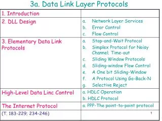
Data Link Layer: Flow Control Stop-and-Wait Data Link Protocols. Such elementary protocols are also called PAR (Positive Acknowledgment with Retransmission) or ARQ (Automatic Repeat reQuest).

Data Link Layer: Flow Control Stop-and-Wait Data Link Protocols
E N D
Presentation Transcript
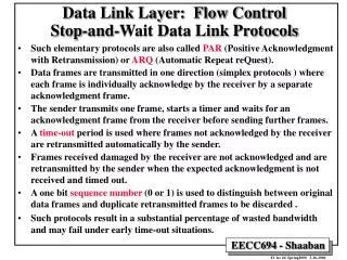
Data Link Layer: Flow ControlStop-and-Wait Data Link Protocols • Such elementary protocols are also called PAR (Positive Acknowledgment with Retransmission) or ARQ (Automatic Repeat reQuest). • Data frames are transmitted in one direction (simplex protocols ) where each frame is individually acknowledge by the receiver by a separate acknowledgment frame. • The sender transmits one frame, starts a timer and waits for an acknowledgment frame from the receiver before sending further frames. • A time-out period is used where frames not acknowledged by the receiver are retransmitted automatically by the sender. • Frames received damaged by the receiver are not acknowledged and are retransmitted by the sender when the expected acknowledgment is not received and timed out. • A one bit sequence number (0 or 1) is used to distinguish between original data frames and duplicate retransmitted frames to be discarded . • Such protocols result in a substantial percentage of wasted bandwidth and may fail under early time-out situations.
Data Frame 4 Data Frame 5 Data Frame 6 Data Frame 1 Data Frame 2 Data Frame 3 Frame transmission time = (d+h)/b b = channel bandwidth One way Channel delay or latency l Sender Receiver : : : : : : Protocol 1: An Unrestricted Simplex Protocol • Transmission in one direction • The receiver is always ready to receive the next frame (has infinite buffer storage). • Error-free communication channel. • No acknowledgments or retransmissions used. • If frame has d data bits and h overhead bits, channel bandwidth b bits/second: maximum channel utilization = data size/frame size = d/(d + h) maximum data throughput = d/ (d + h ) * channel bandwidth = d/ (d + h ) * b : : : : : :
Data Frame 1 Data Frame 2 Time Protocol #2: A Simplex Stop-and-Wait Protocol • Simplex: Data transmission in one direction • The receiver may not be always ready to receive the next frame (finite buffer storage). • Receiver sends a positive acknowledgment frame to sender to transmit the next data frame. • Error-free communication channel assumed. No retransmissions used. • Maximum channel utilization » (time to transmit frame /round trip time) * d/(d + h) »d/ (b * R) • Maximum data throughput » channel utilization * channel bandwidth »d/ (b * R) * b = d/ R Round trip time, R Acknowledgment Frame Sender Receiver Acknowledgment Frame : : : : : :
Data Link Protocol #2 A Simplex Stop-and-Wait Protocol
Round trip time, R Data Frame 1, sequence # 0 Ack Frame, sequence # 0 Time Data Frame 1, sequence # 1 Receiver Sender Ack Frame, sequence # 1 Data Frame 1, sequence # 0 Protocol 3: A Simplex Positive Acknowledgment with Retransmission (PAR) Protocol • The receiver may not be always ready to receive the next frame (finite buffer storage). • Noisy communication channel; frames may be damaged or lost. • Frame not received correctly with probability p • Receiver sends a positive acknowledgment frame to sender to transmit the next data frame. Any frame has a sequence number, either 0 or 1 • Maximum utilization and throughput similar to protocol 2 when the effect of errors is ignored. : : : : : :
Data Frame 1, sequence # 0 Error: Frame lost or damaged, with probability p Time Ack Frame, sequence # 0 Protocol 3: A Simplex PAR Protocol (continued)Effect of Errors • The sender starts a timer when transmitting a data frame. • If data frame is lost or damaged (probability = p): • Receiver does not send an acknowledgment • Sender times out and retransmits the data frame Start timer X Time-out Interval Time-out Retransmit frame Receiver Data Frame 1, sequence # 0 Sender
Data Link Protocol #3 1/2 (sender process) A Simplex positive Acknowledgment with Retransmission Protocol
Data Link Protocol #3 2/2 (receiver process) A Simplex positive Acknowledgment with Retransmission Protocol
Data Link Layer: Flow Control Sliding Window Protocols • These protocols allow both link nodes (A, B) to send and receive data and acknowledgments simultaneously. • Acknowledgments are piggybacked into an acknowledgment field in the data frame header not as separate frames. • If no new data frames are ready for transmission in a specified time, a separate acknowledgment frame is generated to avoid time-out. • Each outbound frame contains a sequence number ranging from 0 to 2 n-1 (n-bit field). N = 1 for stop-and-wait sliding window protocols. • Sending window: A set of sequence numbers maintained by the sender and correspond to frame sequence numbers of frames sent out but not acknowledged. • The maximum allowed size of the sending window w correspond to the maximum number of frames the sender can transmit before receiving any acknowledgment without blocking (pipelining). • All frames in the sending window may be lost or damaged and thus must be kept in memory or buffers until they are acknowledged.
Sliding Window Data Link Protocols • Receiving window:A set of sequence numbers maintained by the receiver and indicate the frames sequence numbers it is allowed to receive and acknowledge. • The size of the receiving window is fixed at a specified initial size. • Any frame received with a sequence number outside the receiving window is discarded. • The sending window and receiving window may not have the same upper or lower limits or have the same size. • When pipelining is used, an error in a frame is dealt with in one of two ways: • Go back n: • The receiver discards all subsequent frames and sends no acknowledgments. • The sender times out and resends all the discarded frames starting with faulty frame. • Selective repeat: • The receiving data link stores all good frames received after a bad frame. • Only the bad frame is retransmitted upon time-out by the sender.
A Sliding Window Protocol of Size 1 with a 3-bit Sequence Number (b) After the first frame has been sent (c) After the first frame has been received (d) After the first acknowledgment frame has been received (a) Initial state
DF 1, seq # 0 Data Frame 1, seq # 0 Data Frame 2, seq # 1 DF 2, seq # 1 DF 3, seq # 2 Ack Frame, seq # 0 DF 4, seq # 3 ACK F, seq # 0 Ack Frame, seq # 1 Data Frame 3, seq # 0 Time Ack Frame, seq # 0 Data Frame 4, seq # 1 Ack Frame, seq # 1 Difference Between PAR and Sliding Window Protocols Positive Acknowledgment with Retransmission Shown Here: Four Data Frames Transmitted Sliding Window sequence # from 0 to 3 Stop-and-Wait Round Trip Time, R Ack F, seq # 1 Ack Frame, seq # 2 Ack Frame, seq # 3 : : : : : : : : : : : : Sender Receiver Sender Receiver
After two frames have been acknowledged After nine frames have been acknowledged A 4-Frame Sending Window Initial window Unacknowledged or Pending Frames
Data Link Protocol #4 1/2A 1-bit Bi-directional Sliding Window Protocol
Data Link Protocol #4 2/2A 1-bit Bi-directional Sliding Window Protocol
Channel Utilization & Data Throughput For Sliding Window Protocols b = Channel bandwidth or transmission rate bits/sec FS = Frame size = # of data bits + # overhead bits = d + h R = Channel round trip time N = Send/receive window size p = Probability frame a data frame is lost or damaged • Ignoring errors, condition to maximize Utilization/Throughput: Time to transmit N frames ³ Round trip time FS/b * N = (d + h)/b * N ³ R Under this condition: Maximum channel utilization » data size/frame size = d/(d + h) Maximum data throughput »d/FS = d/(d + h ) * b • Including the effect of errors only on data frame; assuming selective repeat: On the average p data frames have to be retransmitted Under these condition: Total Data Frame overhead = h + p * FS Maximum channel utilization »d/[(1 + p)*FS] Maximum data throughput »d/[(1 + p)*FS] * b
Two Operation Sequences For Sliding Window Protocol (#4) (a) Normal Protocol Operation: No duplicate packets (b) A special situation: Half the frames contain duplicates * Network layer accepts a packet.
Effect of Errors in Sliding Window Protocols (a) Effect of an error when the receiver size is 1 (b) Effect of an error when the receiver size is large
Finite State Machine Protocol Models • A protocol may be represented by a finite state machine (protocol machine). • States are chosen when the protocol machine is waiting for the next event (i.e sending or receiving a protocol data unit PDU). • The state of the complete protocol is the combination of the state of the two protocol machines and the channel. • The state of the channel depends on its content. • Each state may have one or more transitions to other states when protocol events occur. • Incomplete state machine specification. • Deadlock states.
State Transition Diagram For Protocol 3 • The protocol state machine states are represented by XYZ • X = 0 or 1 depending on the sequence number of the frame the sender is attempting to send. • Y = 0 or 1 depending on the sequence number of the frame the receiver expects. • Z = 0, 1, A or empty (-) corresponding to the state (content) of the channel.
Data Link Protocol Example: HDLC - High-Level Data Link Control • Bit-oriented protocol derived from IBM’s SNA data link protocol SDLC (Synchronous Data Link Control). • Frame Types: Information, Supervisory, Unnumbered. • Uses sliding window with 3-bit sequence numbers. • Uses CRC-CCITT for error control. • Protocol commands include: • DISC (DISConnect) used to disconnect a machine from the line. • SNRM (Set Normal Response Mode) brings a machine online and sets one machine as channel master and the other as slave ( was used for dumb terminals when connected to mainframes). • SABM (Set Asynchronous Balanced Mode). • FRMR (FRaMe Reject) rejects a frame with correct checksum with impossible structure.
HDLC Bit-Oriented Frame Format Information Frame Frame Sequence # Poll/Final Next Frame Expected Supervisory Frame Unnumbered Frame
Data Link For Temporary Internet Host Connection • Serial Line IP (SLIP). • Point-to-Point Protocol (PPP).
Internet Data Link Protocols: Serial Line IP (SLIP) RFC 1055 • Send raw IP packets with a flag byte (0xC0) at the end for framing with character stuffing (data 0xC0 replaced with 0xDB 0xDC). • Recent versions use header compression by omitting header fields in consecutive packets and frames. • Does not include any form of error detection or correction. • Supports only one network protocol: IP (Internet Protocol). • Dynamic IP address assignment not supported. • Lacks any form of authentication.
Internet Data Link Protocols: Point-to-Point Protocol (PPP) • Uses standard HDLC framing byte (01111110) with error detection. • Uses Link Control Protocol (LCP) for brining lines up, option negotiation, and to bring lines down. • Network layer options and configurations are negotiated independent of the network layer used by utilizing different NCPs (Network Control Protocol) packets for each supported network layer. • Support for several packet types by using a protocol field: • Network protocols (protocol field starts with 0): IP, IPX, AppleTalk etc. • Negotiating protocols (protocol field starts with 1): LCP, NCP. • PPP is used for both dial-up network access and for router-to-router communication in subnets.
PPP Frame Format & Transition Diagram PPP Frame Format for unnumbered mode operation. Simplified PPP phase diagram for brining a line up or down.